


SJ300 Inverter
Operations
and Monitoring
4–39
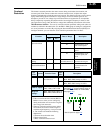
External Brake
Control Function
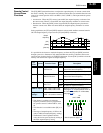
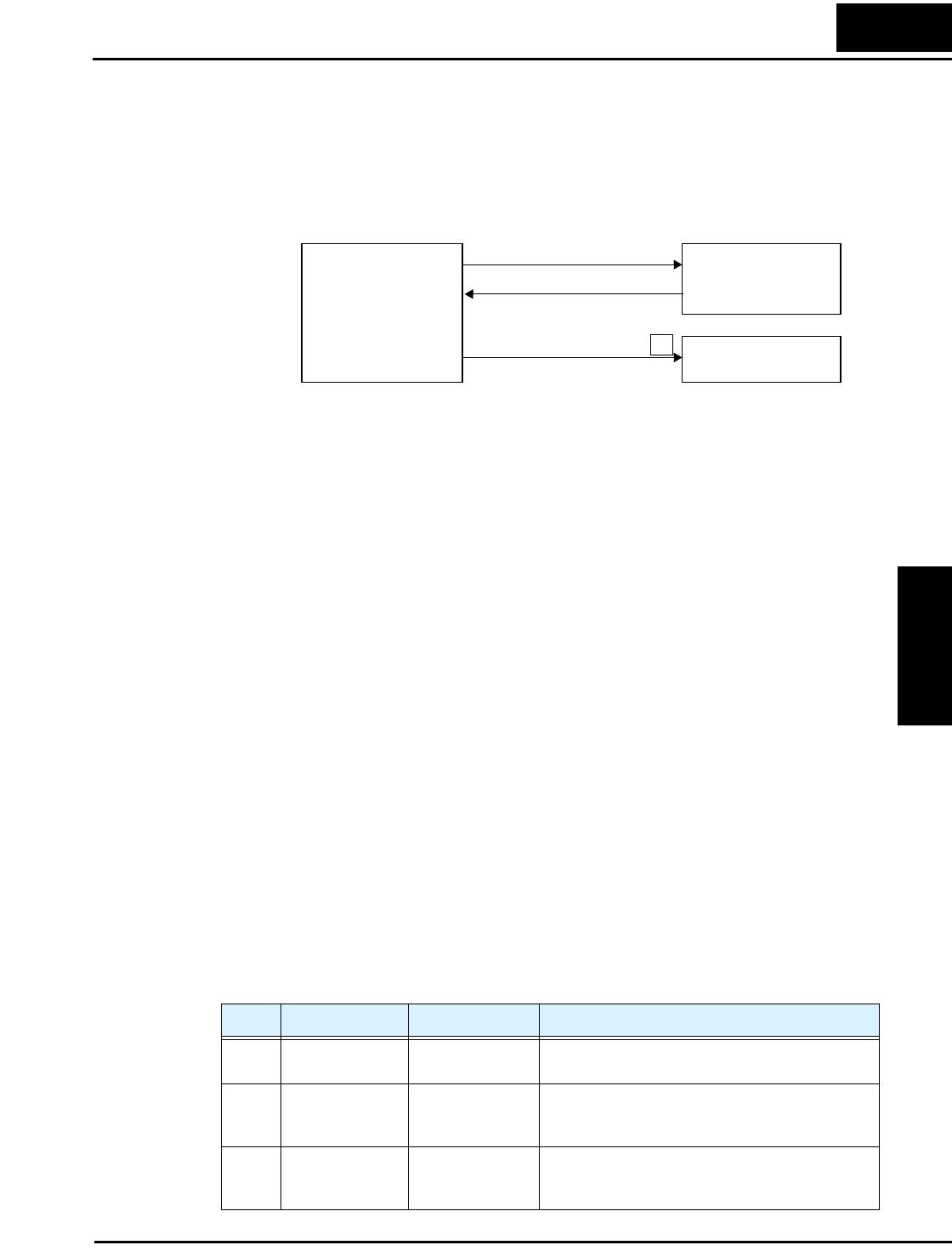
The External Brake Control function enables the inverter to control external electromechanical
brake systems with a particular safety characteristic. For example, elevator control systems
maintain the brake on the load until the drive motor has reached a releasing frequency (point at
which the external mechanical brake is released). This ensures that the load does not have an
opportunity to begin coasting before the inverter begins driving the motor. The External Brake
Control function can be enabled by setting parameter B120=01. The diagram below shows the
signals that are important to this function.
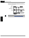
The steps below describe the timing diagram of events on the following page.
1. When the Run command turns ON, the inverter begins to operate and accelerate to releasing
frequency (B125).
2. After the output frequency arrives at the set releasing frequency (B125), the inverter waits
for the brake release confirmation, set by B121. The inverter outputs the braking release
signal [BRK]. However, if the output current of the inverter is less than the releasing current
set by B126, the inverter does not turn ON the brake release output [BRK]. The lack of the
proper current level indicates a fault (such as open wire to motor). In this case, the inverter
trips and outputs the braking error signal [BER]. This signal is useful to engage an
emergency brake to ensure the load does not move, if the primary braking system has failed.
3. While the brake release output [BRK] is ON, the inverter drives the motor but does not
accelerate immediately. The inverter waits for confirmation from the external brake. When
the external brake system properly releases, it signals the inverter by using the Brake OK
input terminal [BOK]. If [BOK] is not assigned to an intelligent input, B124 is ignored.
4. When the brake operates properly and signals with the [BOK] input, the inverter waits for
the required time for acceleration (B122), and then begins to accelerate to the set target
frequency. If [BOK] is not assigned to an intelligent input, acceleration begins after the
delay time set by B122 after [BRK] signal occurs.
5. When the Run command turns OFF, the procedure outlined above happens in reverse. The
idea is to engage the brake before the motor comes completely to a stop. The inverter decel-
erates to the releasing frequency (B125) and turns the brake release output [BRK] OFF to
engage the brake.
6. The inverter does not decelerate further during just the waiting time for brake confirmation
(B121). If the brake confirmation signal does not turn OFF within the waiting time for brake
confirmation, the inverter causes a trip alarm and outputs the brake error signal [BER]
(useful for engaging an emergency brake system).
7. Normally, the brake confirmation signal [BOK] turns OFF, and the inverter waits the
required waiting time. Then the inverter begins to decelerate again and brings motor and
load to a complete stop (see timing diagram on next page).
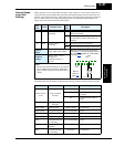
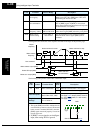
[BRK] Brake release
[BOK] Brake confirmation
Inverter
External Brake
System
Emergency Brake
(or alarm, etc.)
[BER] Brake error
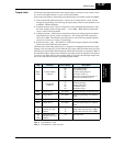
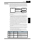
Code Function Data or Range Description
B120 Brake control
enable
00=Disable
01=Enable
Enables external brake control function within the
inverter
B121 Brake waiting
time for release
0.00 to 5.00 sec. Sets the time delay after arrival at release
frequency (B125) before the inverter outputs brake
release signal [BRK]
B122 Brake wait time
for acceleration
0.00 to 5.00 sec. Sets time delay after brake confirmation signal
[BOK] is received until the inverter begins to accel-
erate to the set frequency