


SJ300 Inverter
Operations
and Monitoring
4–17
External Signal
for DC Injection
Braking
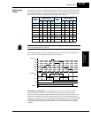
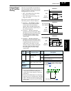
When the terminal [DB] is turned ON, the
DC braking [DB] feature is enabled. Set the
following parameters when the external DC
braking terminal is to be used:
• A053 – DC braking delay time setting.
The range 0.0 to 5.0 seconds.
• A054 – DC braking force setting. The
range is 0 to 100%.
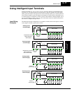
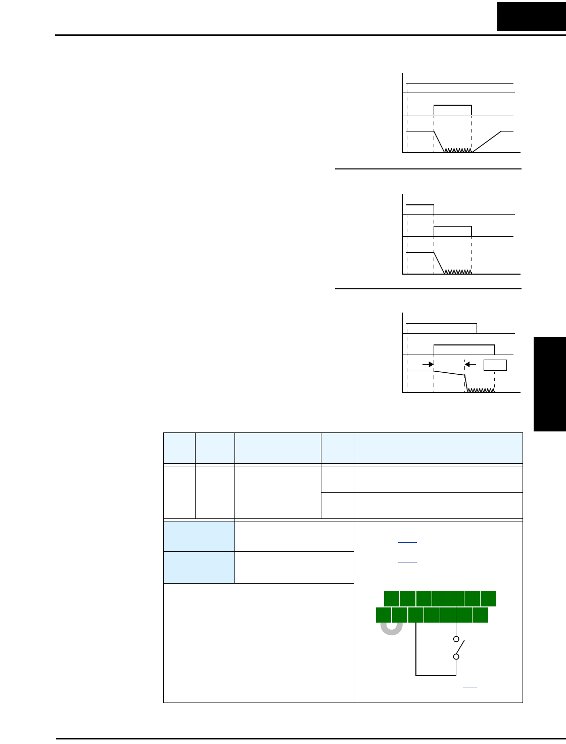
The scenarios to the right help show how
DC braking works in various situations.
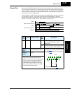
1. Scenario 1 – The [FW] Run or [RV]
Run terminal is ON. When the [DB]
terminal turns ON, DC braking is
applied. When the [DB] terminal turns
OFF again, the inverter output ramps to
the previous frequency.
2. Scenario 2 – The Run command is
applied from the operator keypad. When
the [DB] terminal turns ON, DC braking
is applied. When the [DB] terminal
turns OFF again, the inverter output
remains OFF.
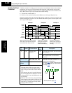
3. Scenario 3 – The Run command is
applied from the operator keypad. When
the [DB] terminal turns ON, DC braking
is applied after the delay time set by
A053 expires. The motor is in a free-
running (coasting) condition during this
delay time. When the [DB] terminal
turns OFF again, the inverter output
remains OFF.
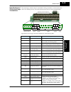
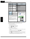
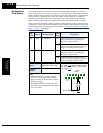
Opt.
Code
Symbol Function Name
Input
State
Description
07 DB External Signal for
DC Injection
Braking
ON applies DC injection braking during
deceleration
OFF does not apply DC injection braking
during deceleration
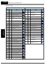
Valid for
inputs:
C001, C002, C003, C004,
C005, C006, C007, C008
Required
settings:
A053, A054
Notes:
• Do not use the [DB] input continuously or for
a long time when the DC braking force
setting A054 is high (depends on the motor
application).
• Do not use the [DB] feature for continuous or
high duty cycle as a holding brake. The [DB]
input is designed to improve stopping perfor-
mance. Use a mechanical brake for holding a
stop position.
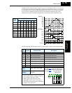
Output
frequency
[FW, RV]
[DB]
Scenario 1
Output
frequency
Run command
from operator)
Scenario 2
Output
frequency
Scenario 3
[DB]
Run command
from operator)
[DB]
A053
t
t
t
delay
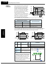
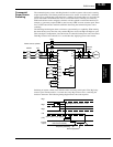
5 3 1
7 6 4 2
8
FW
TH
PLC
CM1
P24
CM1
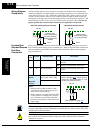
See I/O specs on page 4–9.
Example: (Requires input configuration—
see page 3–47
. Jumper position shown is
for –xFU/-xFR models; for –xFE models,
see page 4–12
.)
DB