


SJ300 Inverter
Troubleshooting
and Maintenance
6–15
General Inverter
Electrical
Measurements
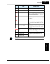
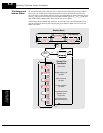
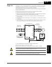
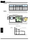
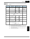
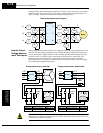
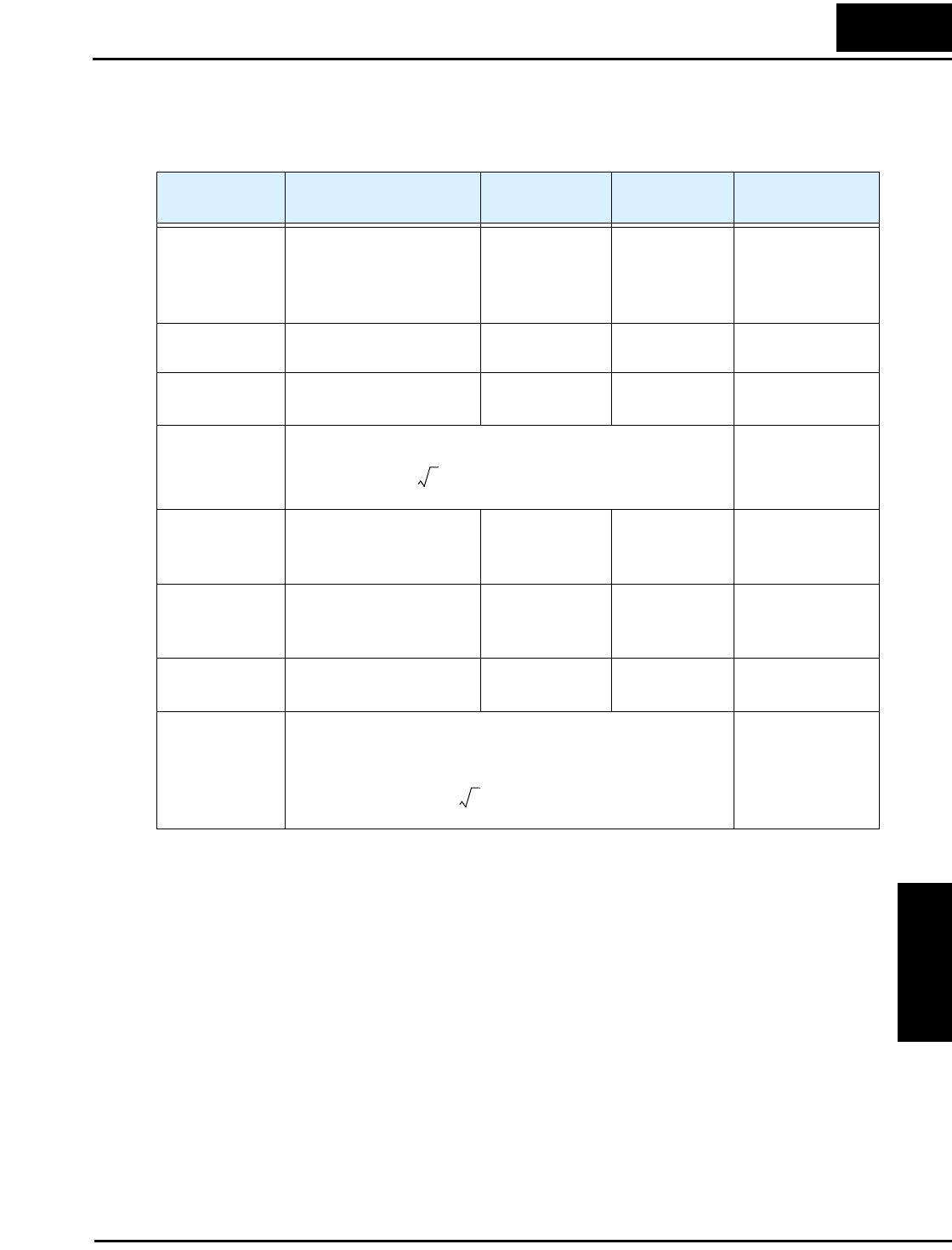
The following table specifies how to measure key system electrical parameters. The diagrams
on the next page show inverter-motor systems and the location of measurement points for these
parameters.
Note 1: Use a meter indicating a fundamental wave effective value for voltage, and meters
indicating total effective values for current and power.
Note 2: The inverter output has a distorted waveform, and harmonic frequencies may cause
erroneous readings. However, the measuring instruments and methods listed above
provide reasonably accurate results.
Note 3: A general-purpose digital volt meter (DVM) is not usually suitable to measure a
distorted waveform (not pure sinusoid).
Parameter
Circuit location
of measurement
Measuring
instrument
Notes Reference Value
Supply voltage
E
1
E
R
– across L1 and L2
E
S
– across L2 and L3
E
T
– across L3 and L1
Moving-coil type
voltmeter or recti-
fier type voltmeter
Fundamental
wave effective
value
Commercial supply
voltage (200V class)
200-240V, 50/60 Hz
400V class 380-
460V, 50/60 Hz
Supply current
I
1
I
r
– L1, I
s
– L2, I
t
– L3 Moving-coil type
ammeter
Total effective
value
—
Supply power W
1
W
11
– across L1 and L2
W
12
– across L2 and L3
Electronic type
wattmeter
Total effective
value
—
Supply power
factor Pf
1
—
Output voltage
E
0
E
U
– across U and V
E
V
– across V and W
E
W
– across W and U
Rectifier type
voltmeter
Total effective
value
—
Output current I
o
I
U
– U
I
V
– V
I
W
– W
Moving-coil type
ammeter
Total effective
value
—
Output power W
o
W
01
– across U and V
W
02
– across V and W
Electronic type
wattmeter
Total effective
value
—
Output power
factor Pf
o
Calculate the output power factor from the output voltage E, output
current I, and output power W.
—
Pf
1
W
1
3E
1
× I
1
×
------------------------------
100%×=
Pf
0
W
0
3E
0
× I
0
×
------------------------------
100%×=