


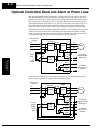
Optional Controlled Decel and Alarm at Power Loss
Operations
and Monitoring
4–6
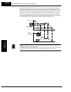
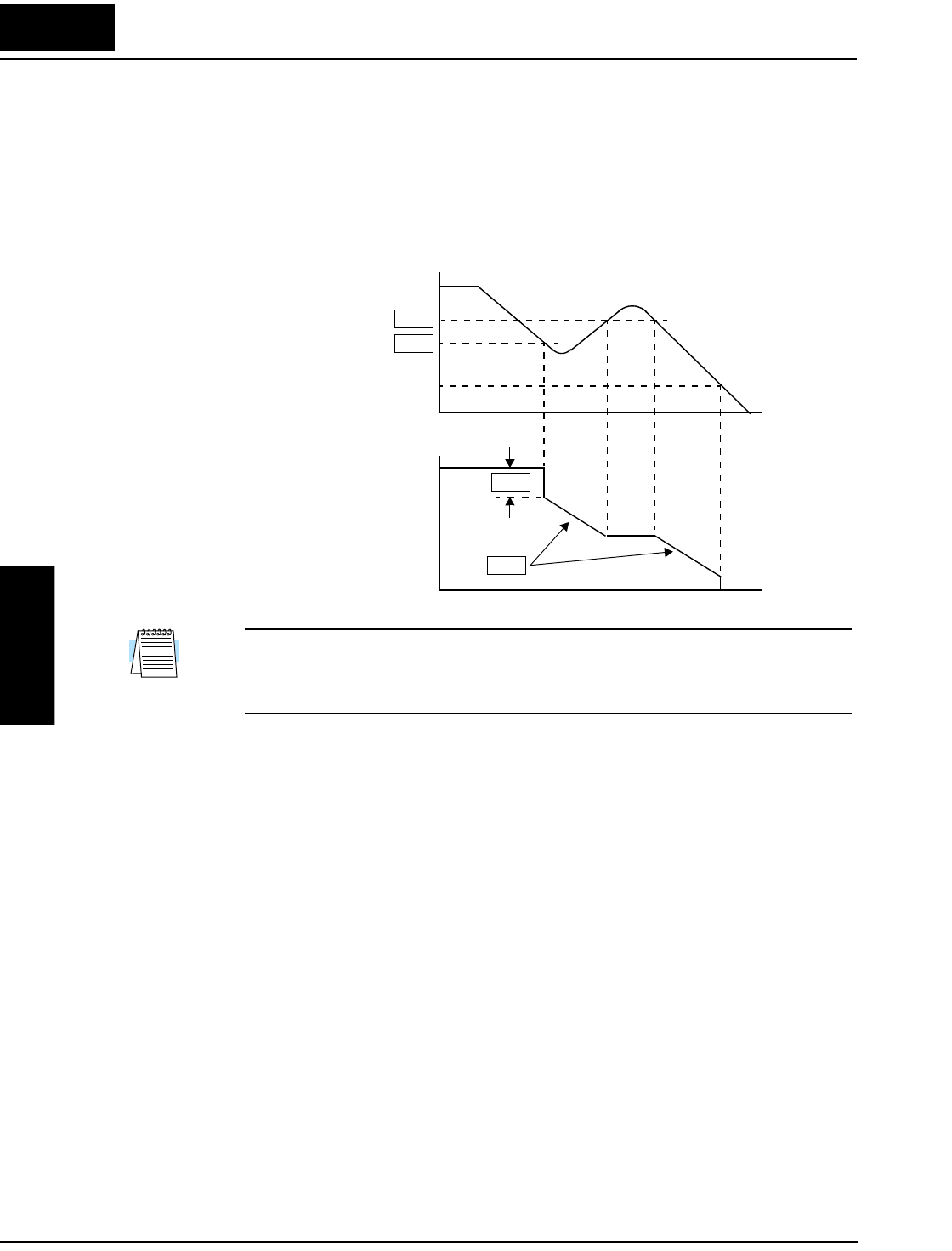
The timing diagram below shows a power loss scenario and the related parameter settings.
During the controlled deceleration the inverter itself acts as a load to decelerate the motor. With
either a high-inertia load or a short deceleration time (or both), it is possible that the inverter
impedance will not be low enough to continue linear deceleration and avoid an over-voltage
condition on the DC bus. Use parameter B052 to specify a threshold for the over-voltage. In
this case, the inverter pauses deceleration (runs at constant speed). When the DC bus decays
again below the threshold, linear deceleration resumes. The pause/resume process will repeat as
necessary until the DC bus energy is depleted (under-voltage condition occurs).
NOTE: (1) Be sure to set the over-voltage threshold greater than the DC bus voltage trigger
level (B052 > B051) for proper operation.
(2) Once the power loss deceleration function starts, it will complete and stop the motor even if
input power is restored. In that case, it automatically enables the Run mode again.
DC bus (V)
Output
Frequency
Under-voltage
level
B052
B051
B054
B053
t
t
0
0