


Using Intelligent Input Terminals
Operations
and Monitoring
4–26
Analog Input
Current/Voltage
Select
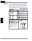
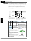
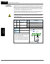
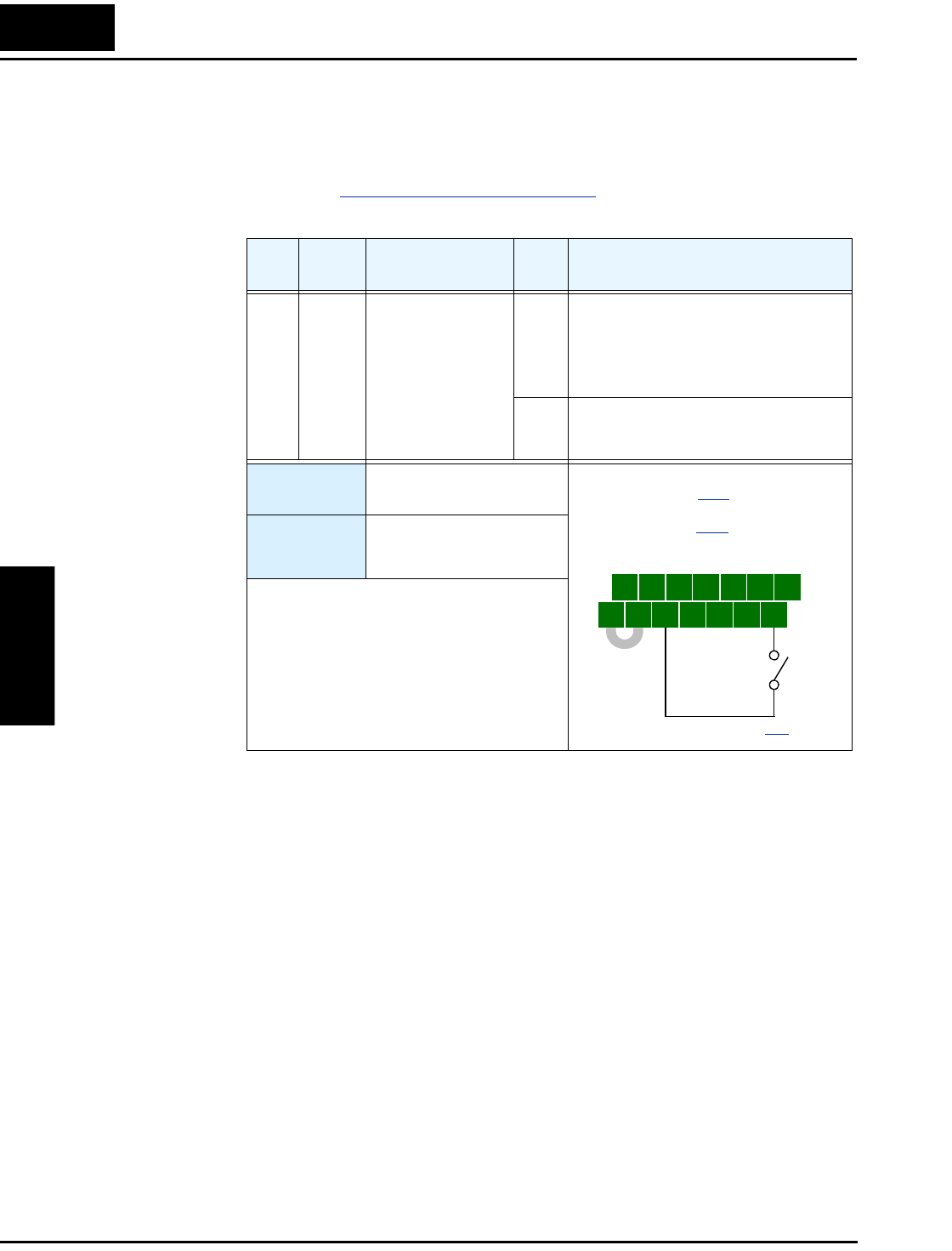
The [AT] terminal operates in conjunction with parameter setting A005 to determine the analog
input terminals that are enabled for current or voltage input. Setting A006 determines whether
the signal will be bipolar, allowing for a reverse direction range. Note that current input signal
cannot be bipolar and cannot reverse direction (must use [FW] and [RV] command with current
input operation). The following table shows the basic operation of the [AT] intelligent input.
Please refer to “
Analog Input Operation” on page 4–59 for more information on bipolar input
configuration, and the operating characteristics of analog inputs.
Opt.
Code
Symbol Function Name
Input
State
Description
16 AT Analog Input
Voltage/current
Select
ON • With A005 = 00, [AT] will enable
terminals [OI]–[L] for current input,
4 to 20mA
• With A005=01, [AT] will enable termi-
nals [O2]–[L] for voltage input
OFF Terminals [O]–[L] are enabled for voltage
input (A005 may be equal to 00 or 01) in
this case
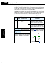
Valid for
inputs:
C001, C002, C003, C004,
C005, C006, C007, C008
Required
settings:
A001 = 01
A005 = 00 / 01
A006 = 00 / 01 / 02
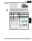
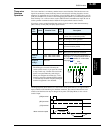
Notes:
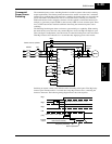
• Be sure to set the frequency source setting
A001=01 to select the analog input terminals.
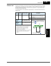
5 3 1
7 6 4 2
8
FW
TH
PLC
CM1
P24
CM1
See I/O specs on page 4–9.
Example: (Default input configuration
shown—see page 3–47
. Jumper position
shown is for –xFU/-xFR models; for –xFE
models, see page 4–12
.)
AT