


“C” Group: Intelligent Terminal Functions
Configuring Drive
Parameters
3–56
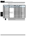
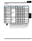
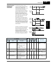
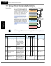
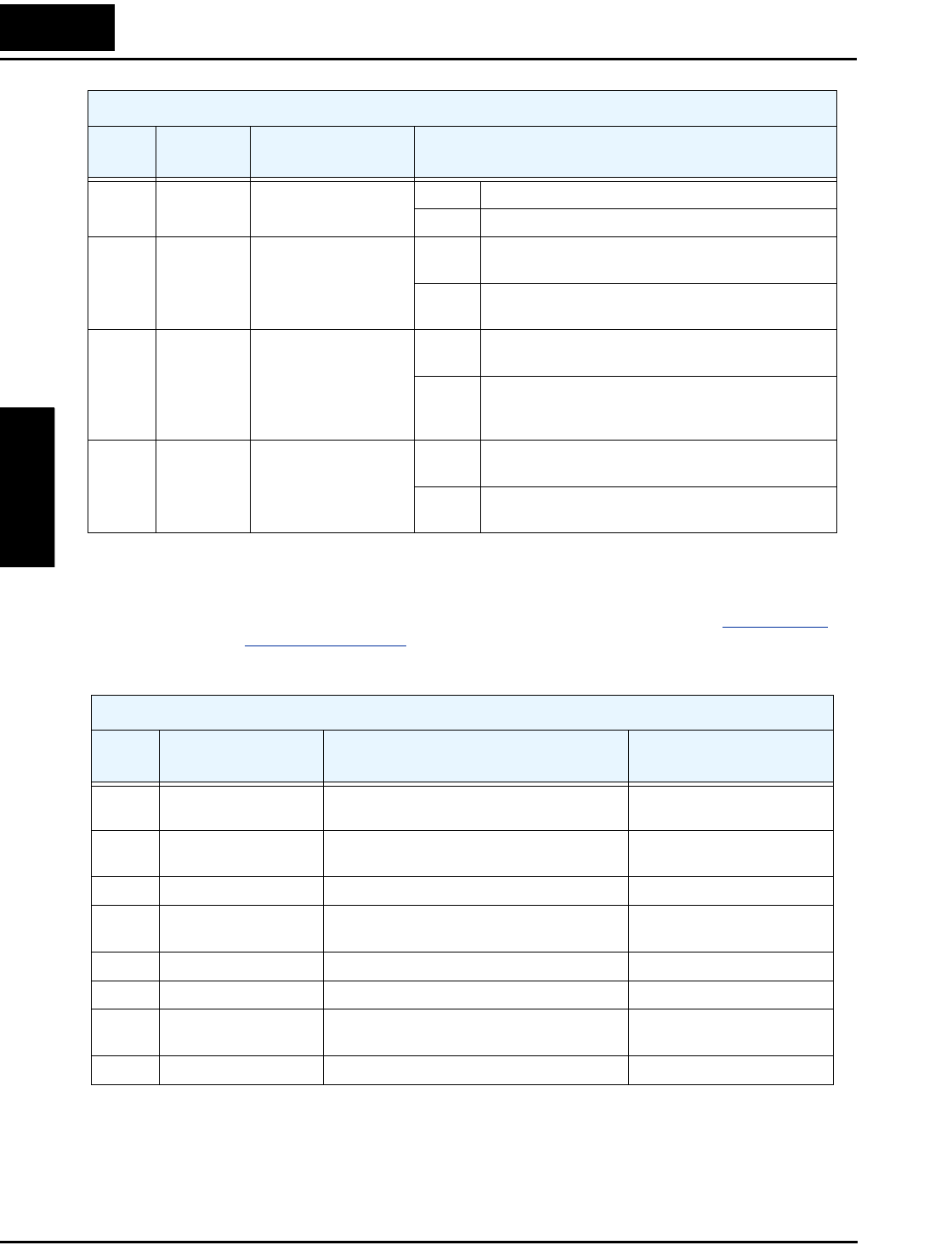
Analog Summary Table - The following table shows all eight functions available for assign-
ment to the three analog output terminals [FM], [AM], [AMI] at a glance. Detailed descrip-
tions, related parameters and settings, and example wiring diagrams are in “
Analog Output
Operation” on page 4–62.
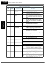
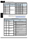
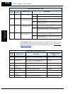
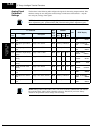
23 POK Positioning completion ON when the load position is at the target
OFF when the load position is not yet at the target
24 FA4 Frequency arrival type
4 – over-frequency (2)
ON when output to motor is at or above the FA threshold
2 (C045) during accel
OFF when the output to motor is below the FA threshold 2
(C046) during decel
25 FA5 Frequency arrival type
5 – at frequency (2)
ON when output to motor is at the FA threshold 2 (C045)
during accel, or at C046 during decel
OFF when the output to motor is not at either the FA
threshold 2 (C045) during accel or at C046 during
decel
26 OL2 Overload notice
advance signal (2)
ON when output current is more than the set Threshold 2
for the overload signal (set with C111)
OFF when output current is less than the set Threshold 2
for the overload signal
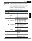
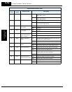
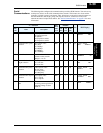
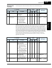
Output Function Summary Table
Option
Code
Terminal
Symbol
Function Name Description
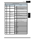
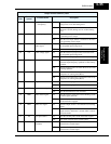
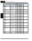
Analog Output Function Summary Table
Option
Code
Function Name Description
Corresponding Signal
Range
00 Output frequency Actual motor speed, represented by PWM
signal
0 to max. frequency in Hz
01 Output current Motor current (% of maximum rated output
current), represented by PWM signal
0 to 200%
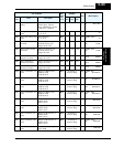
02 Output torque Rated output torque 0 to 200%
03 Digital output
frequency
Output frequency (available only at FM
output)
0 to max. frequency in Hz
04 Output voltage Rated output voltage to motor 0 to 100%
05 Input power Rated input power 0 to 200%
06 Electronic thermal
overload
Percentage of electronic overload attained 0 to 100%
07 LAD frequency Internal ramp generator frequency 0 to max. frequency in Hz