


SJ300 Inverter
Getting Started
1–15
Intelligent
Functions and
Parameters
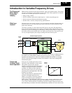
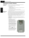
Much of this manual is devoted to describing
how to use inverter functions and how to config-
ure inverter parameters. The inverter is micro-
processor-controlled, and has many independent
functions. The microprocessor has an on-board
EEPROM for parameter storage. The inverter’s
front panel keypad provides access to all
functions and parameters, which you can access
through other devices as well. The general name
for all these devices is the digital operator, or
digital operator panel. Chapter 2 will show you
how to get a motor running, using a minimal set
of function commands or configuring parame-
ters.
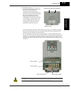
The optional read/write programmer will let you
read and write inverter EEPROM contents from
the programmer. This feature is particularly
useful for OEMs who need to duplicate a partic-
ular inverter’s settings in many other inverters in
assembly-line fashion.
Braking In general, braking is a force that attempts to slow or stop motor rotation. So it is associated
with motor deceleration, but may also occur even when the load attempts to drive the motor
faster than the desired speed (overhauling). If you need the motor and load to decelerate
quicker than their natural deceleration during coasting, we recommend installing a braking
resistor. The dynamic braking unit (built into certain SJ300 models) sends excess motor energy
into a resistor to slow the motor and load (see “
Introduction” on page 5–2 and “Dynamic
Braking” on page 5–6 for more information). For loads that continuously overhaul the motor
for extended periods of time, the SJ300 may not be suitable (contact your Hitachi distributor).
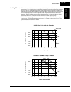
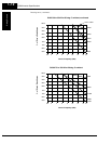
The inverter parameters include acceleration and deceleration, which you can set to match the
needs of the application. For a particular inverter, motor, and load, there will be a range of
practically achievable accelerations and decelerations.
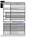
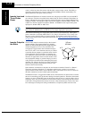
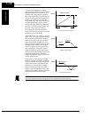
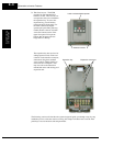
Velocity Profiles The SJ300 inverter is capable of sophisti-
cated speed control. A graphical representa-
tion of that capability will help you
understand and configure the associated
parameters. This manual makes use of the
velocity profile graph used in industry
(shown at right). In the example, the acceler-
ation is a ramp to a set speed, and the decel-
eration is a decline to a stop.
Fixed speed
Accel Decel
t
Speed
Velocity Profile