


SJ300 Inverter
Inverter Mounting
and Installation
2–3
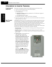
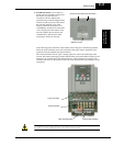
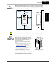
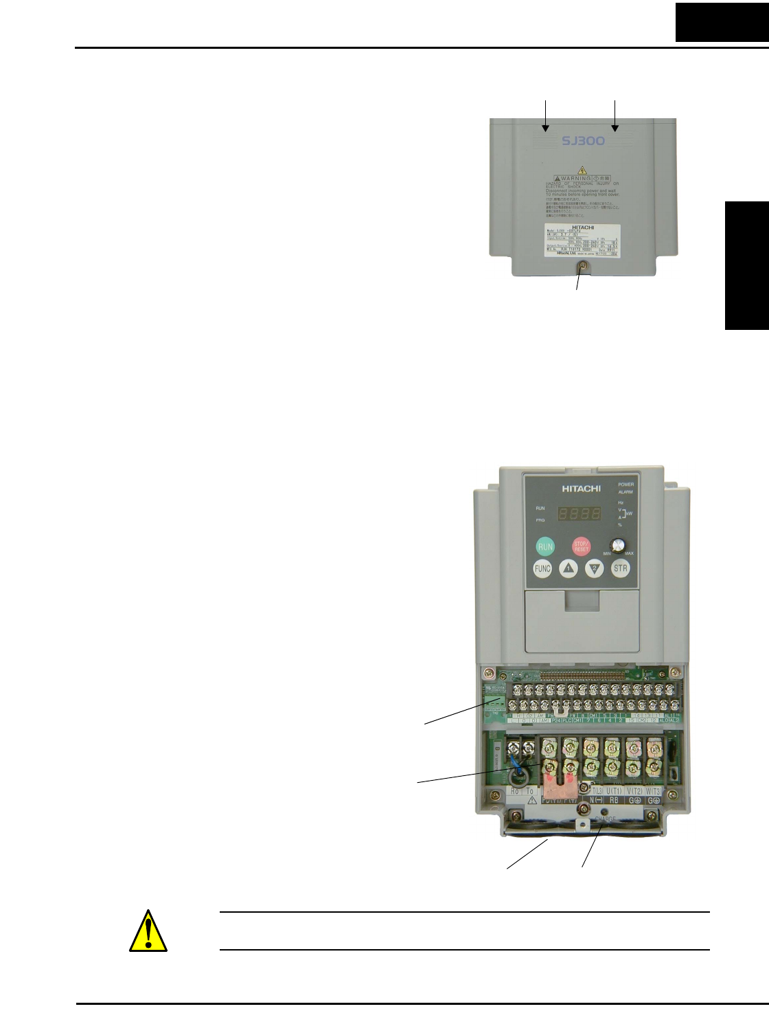
2. Second-level access - First, ensure no
power source of any kind is connected to
the inverter. If power has been
connected, wait five minutes after
powerdown and verify the Charge Lamp
indicator is OFF to proceed. Then locate
the recessed retention screw at the
bottom of the main front panel. Use a
small Phillips screwdriver to remove the
screw. Press the two latch release areas
near the “SJ300” label as shown, and
simultaneously slide the lower front
downward to release for removal.
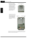
Notice the large power terminals at the bottom of the wiring area. The rubber grommets
below the power terminals are for wire entry/exit to the power source and motor. Never
operate the inverter with the front panel removed.
The control terminals connect logic or analog signals for control and monitoring of the
inverter. The nearby alarm relay provides both normally-open and normally-closed logic for
interface to an external alarm. The alarm circuit may carry hazardous live voltages even
when the main power to the inverter is OFF. So, never directly touch any terminal or circuit
component.
WARNING: Be sure to wait five minutes after powerdown and verify the charge lamp indica-
tor is OFF to proceed. Otherwise there is the risk of electric shock.
Press here and slide cover downward
Retention screw
Wire entry/exit plate
Logic Connector
Power terminals
Charge lamp indicator