


SJ300 Inverter
Operations
and Monitoring
4–15
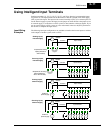
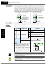
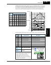
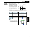
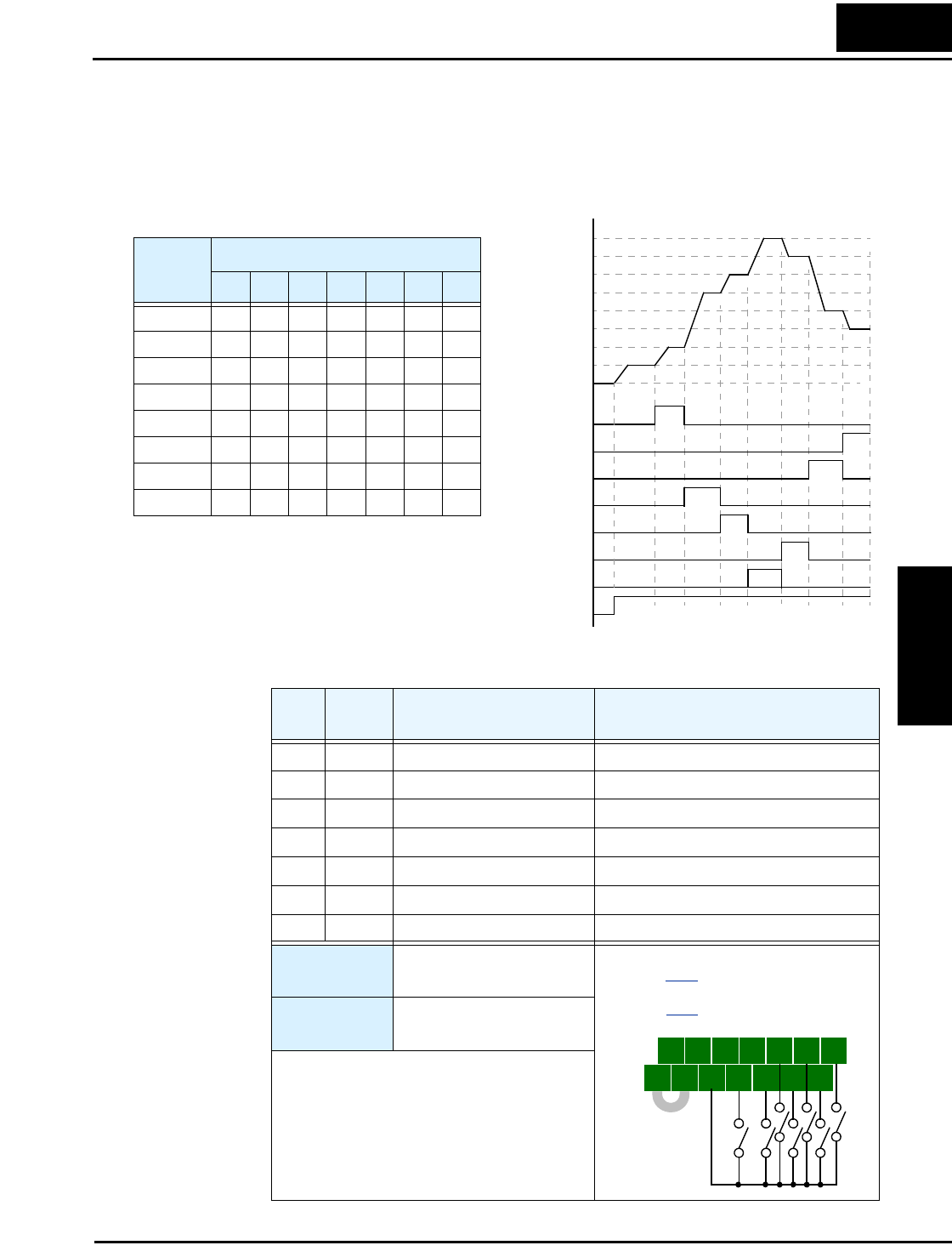
The Bit Operation method of speed control uses up to seven intelligent inputs to select from up
to eight speeds. Since the all-switches-OFF combination selects the first speed, you only need
N-1 switches to select N speeds. With Bit Operation speed control, only one input is normally
active at a time. If multiple switches are ON, the lower numbered input takes precedence
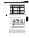
(determines the speed). The table and figure below show how the input combinations work.
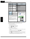
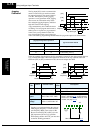
The following table lists the option codes for assigning [SF1 to [SF7] to the intelligent inputs.
0th
SF1
SF2
SF3
3rd
4th
2nd
5th
1st
7th
6th
Speed
Switches
Fwd Run
SF4
SF5
SF6
SF7
Multi-
speed
Input Function
SF7 SF6 SF5 SF4 SF3 SF2 SF1
Speed 0 0000000
Speed 1 —————— 1
Speed 2 ————— 1 0
Speed 3 — — — — 1 0 0
Speed 4 ———1000
Speed 5 ——10000
Speed 6 —100000
Speed 7 1000000
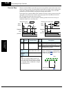
Opt.
Code
Symbol Function Name Description
32 SF1 Bit-level speed select 1 Bit-level speed select, Bit 0
33 SF2 Bit-level speed select 2 Bit-level speed select, Bit 1
34 SF3 Bit-level speed select 3 Bit-level speed select, Bit 2
35 SF4 Bit-level speed select 4 Bit-level speed select, Bit 3
36 SF5 Bit-level speed select 5 Bit-level speed select, Bit 4
37 SF6 Bit-level speed select 6 Bit-level speed select, Bit 5
38 SF7 Bit-level speed select 7 Bit-level speed select, Bit 6
Valid for
inputs:
C001, C002, C003, C004,
C005, C006, C007, C008
Required
settings:
F001, A020 to A035
A019=01
Notes:
• When all [SFx] inputs are OFF, the speed is
set by default to the value in F001.
• When a multi-speed setting more than
50Hz(60Hz) is to be set, it is necessary to
program the maximum frequency A004 high
enough to allow that speed.
5 3 1
7 6 4 2
8
FW
TH
PLC
CM1
P24
CM1
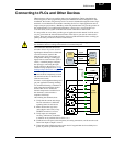
Example: (Requires input configuration—
see page 3–47
. Jumper position shown is
for –xFU/-xFR models; for –xFE models,
see page 4–12
.)
SF1SF3SF5SF7
SF2SF4SF6