This soft copy for use by IBM employees only.
•
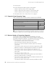
The VPI value is always 0 on the UNI and SSI links. On the NNI links, the VPI
value is as defined in the SET LOGICAL_LINK command for that NNI link.
•
The VCI values 0 through 31 are always reserved for ITU and ATM Forum.
•
The 127 odd-numbered VCIs between 32 and 286 (that is VCI 33, 35, 37, etc.,
through 285) are reserved for point-to-multipoint connections.
•
The even-numbered VCIs between 32 and 286 (32, 34, 36, etc., through 286)
and all the VCIs from 287 up to and including 1023 can be used by the SVCs.
•
The VPI/VCI allocation algorithm is to increment the highest previously
allocated VCI value and verify that this value is not in use by a VC or a VP
connection. When incrementing the VCI value, the following considerations
apply:
− If the connection is a point-to-point connection and the currently highest
allocated VCI is less than 286, the VCI value is incremented by two.
− If the connection is a point-to-point connection and the currently highest
allocated VCI is 286 or higher, the VCI value is incremented by one.
− If the connection is a point-to-multipoint connection, the VCI value is
incremented by one.
− If the currently allocated VCI value for the point-to-point connections is
1023, the next VCI allocated will be the first free VCI value starting from
32.
− If the currently allocated VCI value for the point-to-multipoint connections
is 285, the next VCI allocated will be the first free VCI value starting from
33.
For PVCs, as described in 5.1.5, “How to Configure PVCs” on page 83, you can
either specify the VPI/VCI values allocated to the PVC at the two ports, which are
the endpoints of the PVC, or you may leave it to the 8285 to select the VPI/VCIs
which are allocated. If you choose the latter, the 8285 will use the algorithm
described for SVCs to allocate the VPI/VCI values. For the intermediate links on
a PVC, it is always up to the 8285 to allocate the VPI/VCI values using the
previous algorithm.
For PVPs, as described in 5.1.7, “How to Define PVPs” on page 85, you can
either specify the VPI value allocated to the PVP at the two ports, which are the
endpoints of the PVP or you may leave it to the 8285 to select the VPI/VCIs which
are allocated. If you choose the latter, the 8285 will increment the highest
previously allocated VPI and check to see if this value is not already in use.
When the VPI value reaches the upper bound of VPI (15), the next VPI value
wraps to 0. For intermediate links on a PVP, it is always up to the 8285 to
allocate the VPI values using the previous algorithm.
5.1.9 How Point-to-Multipoint Connections Are Supported
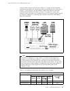
To support point-to-multipoint connections, one cell destined for multiple ports
occupies only one cell location in the shared switch memory. However, multiple
output queues (one per media module) point to that one cell location. When the
multicast cell arrives at the top of the output queue, it is sent to the output
module. Within the output module, if the point-to-multipoint connection spans
over multiple ports, then the multicast cell is replicated as required. The switch
keeps track of when the last output port has transmitted the cell, thereby
allowing its memory locations to be freed. This technique minimizes the amount
of memory space required for multicast messages.
Chapter 5. 8285 ATM Network Specifications 87


