


This soft copy for use by IBM employees only.
the IBM 8285 is installed without the expansion unit, the switching is
done as follows:
a. The cell is switched from CAD_Up to CAD_Down immediately as well
as the case of point-to-point connection. The CAP_Up does not
recognize the multicast ID.
When the IBM 8285 installed with the expansion unit, the switching is
done as follows:
a. The switch chip recognizes that the TB is actually a Multicast ID;
thus, using the MID as a pointer, it looks at its switch multicast tree
table to get 16 bits. Each bit corresponds to a blade. If the bit is on,
then that blade is part of the multicast tree.
b. The switch chip switches the cell to the target blades based on the
multicast tree table.
2. Receive the cell into the target blade.
This step is the same as in a point-to-point connection described earlier.
3. Place the cell in the correct output queue and prepare for transfer to
SFE_Down.
a. Using SB and LCBA, CAP_Down determines LCBAdown. Since this
is a multicast connection, LCBAdown actually points to a chain of
LCBs. Each LCB in the chain represents the branches on the
multicast tree on this blade. Each LCB in the chain has VPI/VCI out,
SWAP_TYPE and target port (TP) and last multicast (Last_MC)
indication. There is also a shadow of the LCB chain in CAD_Store
for performance reasons.
b. The same steps as in the unicast case apply. But when the cell has
been sent to SFE_Down, the CAD_Down will re-enqueue this cell in
the general queue so that CAP will reprocess this cell with the next
LCB in the chain. This is done till CAP_Down finds the LAST_MC
indication in the LCB.
4. Prepare and send a new ATM cell.
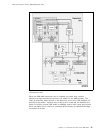
These scenarios assume that the appropriate tables have been assembled
already by the 8285 ATM Control Point and stored in the appropriate CAP/CAD.
This would be done, for instance, during the call establishment process. To
communicate such information to internal devices (such as CAD, CAP, an SFE),
the 8285 ATM Control Point uses a special port number, F (which is unique
within the switch), and special internal cells, called guided cells, which can be
discriminated from the other internal cells, called swapped cells, by its format
field.
3.3 Control Point Codes
There are three types of control point microcode:
•
Boot Code
This resides in flash memory on the control point and is the first thing that
executes after a power-on or reset. It contains initialization, diagnostics and
support for download out-of-band commands. This code executes straight
from flash memory and is normally used to load the operational code.
•
Operational Code
28 ATM Workgroup Solutions: Implementing the 8285 ATM Switch