This soft copy for use by IBM employees only.
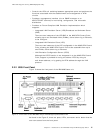
•
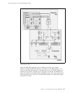
Management and Control Components:
− Control Point components:
- Processing Components
•
Flash memory, to store the microcode
•
8M byte DRAM, for operational code and tables
•
Motorola M68040 processor, to execute the microcode
- Management Components:
•
M360 processor, to handle the console interface (the same as the
IBM 8260)
•
Data Handling Components:
− CAP/CAD components to process cells, both inbound and outbound
− Specific Front End (SFE) components to handle the physical interfaces,
inbound and outbound, for all ATM ports, including:
- ATM 25 Mbps ports
- ATM 155 Mbps port. While this SFE is physically located on the
optional 155 Mbps ATM I/O Card, it can be treated as functionally
part of the base unit.
- ATM control-point port.
3.1.1.1 8285 ATM Control Point
The 8285 ATM Control Point has a processor and flash memory. The flash
memory holds the boot strap code and also the operational code. The control
point performs the following functions:
•
Signalling entities
•
Resource management
•
Address mapping
•
Topology and route selection
•
Node management and inband or out-of-band console interface
•
Integrated LES/BUS
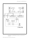
The control point manages the rest of the ATM subsystem by sending control
cells via an internal port connected to the 25 Mbps HS.SFE.
3.1.1.2 CAP, CAD and SFE
The CAP, CAD and SFE are internal components implemented on the IBM 8285
Base Unit, as well as in each of the ATM modules. Their functions are as
follows:
•
CAP/CAD Components:
− CAP (Common ATM Processor)
The CAP handles the cell routing, queuing, scheduling, and traffic
management. It determines what the routing header for the internal cell
should be and gives the information to the CAD to build the cell.
− CAD (Common ATM Datamover)
Chapter 3. Functional Overview of the IBM 8285 19


