This soft copy for use by IBM employees only.
connection between CAD_Up and CAD_Down in the base unit is
disabled.
b. When the switch chip indicates to CAD_Up to give the next cell,
CAD_Up gives the first cell from the appropriate queue based on its
priority mechanism (RB over NRB Queue)
c. The cell is delivered to the switch chip, and the pointers of that
queue are updated.
d. The switch chip switches the cell based on TB.
5. Receive the cell into the target blade.
a. CAD_Down has prepared a location in advance for the next cell.
b. CAD_Down receives the cell into CAD_Store in the general queue.
c. CAD_Down dequeues the cell and sends CAP_Down a copy of the
RH, which contains the LCBAup and the source blade.
6. Place the cell in the correct output queue and prepare it for transfer to
SFE_Down.
a. Using SB and LCBAup, CAP_Down determines LCBAdown.
LCBAdown points to the LCB for the connection in the outbound
blade. The LCB has VPI/VCI out, target port (TP), RB/NRB and
Multicast indication. There is also part of the LCB in a shadow zone
in CAD_Store for performance reasons.
b. LCBAdown TP, NRB/RB, and Multicast indications from the LCB are
given to CAD_Down.
CAD_Down queues the cell in the corresponding target port queue (one
RB and one NRB per port) with the indication received from CAP_Down
and prepares it for transfer to SFE_Down.
7. Prepare and send a new ATM cell.
a. When SFE_Down asks for the next cell of a port, CAD_Down moves
the contents of LCBshadow, which has VPI/VCI out and the type of
swapping (SWAP_TYPE) to be performed, plus the 52-byte cell to
SFE_Down.
b. SFE_Down modifies the header based on SWAP_TYPE. SWAP_TYPE
indicates if only the VP needs to be swapped, if both the VP and VC
need to be swapped or neither need to be swapped. The PTI field is
always retrieved from the incoming header.
c. SFE generates HEC.
d. SFE presents the cell to the specific interface.
•
Point-to-Multipoint Routing
In a point-to-multipoint (multicast) connection, the process is very similar.
Steps remain the same right up until the cell is ready to be switched. The
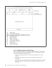
TB field actually indicates that this cell is part of a multicast connection by
having the first bit of TB set to 1. The other 7 bits form the multicast ID
(MID). In a point-to-point connection, the first bit is set to 0 and the other 7
bits indicate the target blade.
1. Switch the cell.
This step depends on the IBM 8285 has a expansion unit or not. In other
words, the switching is done by the CAP/CAD or the switch chip. When
Chapter 3. Functional Overview of the IBM 8285 27


