


This soft copy for use by IBM employees only.
The CAD function prepares the cell for transmission to the switch. The
CAD builds the internal cell in its RAM according to instructions given by
the CAP.
As described in 3.1, “IBM 8285 Architecture Overview” on page 17, the IBM
8285 base unit is treated as a single module and all ports in the base unit
share two sets of CAP/CAD, one set to handle the inbound cells, called
CAP_up and CAD_up, and the other set to handle the outbound cells, called
CAP_down and CAD_down.
•
SFE (Specific Front End)
The SFE handles the ATM front-end concentration and dispatch. Its main
role is to deliver the cell from any ATM interface to the CAD.
There are three sets of SFE components in the base unit: an
inbound/outbound pair for the ATM25 ports, called HS.SFE_up/HS.SFE_down,
an inbound/outbound pair for the ATM155 port, called SFE_up/SFE_down, and
a single, bidirectional SFE used by the control point, called the CP SFE.
In addition, each ATM module also uses CAP, CAD, and SFE components, but in
two sets: an inbound set (CAP_Up, CAD_Up, and SFE_Up), and an outbound set
(CAP_Down, CAD_Down, and SFE_Down). Note that this slightly different from
the 8285 switch which has the additional CP SFE, and which connects CAD_up
directly to CAD_down when operating without an expansion unit.
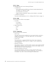
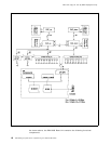
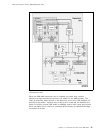
Figure 10 on page 21 shows the hardware architecture of the IBM 8285 Base
Unit when connected to the IBM 8285 Expansion Chassis.
20 ATM Workgroup Solutions: Implementing the 8285 ATM Switch