


9
2 Installing and Removing the Intel® Blade
Server Ethernet Switch Module IXM5414E
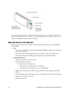
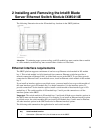
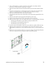
The following illustration shows the I/O module bay locations in the SBCE platform.
Attention: To maintain proper system cooling, each I/O module bay must contain either a module
or a filler module; each blade bay must contain either a blade or a filler blade.
Ethernet interface requirements
The SBCE platform supports a minimum of one hot-swap Ethernet switch module in I/O module
bay 1. This switch module is a fully functional four-connector Ethernet switch that provides a
network connection to Ethernet Link 1 in all the blade servers in the SBCE. To provide a network
connection for Ethernet Link 2 in each blade server, install an Ethernet switch module in I/O module
bay 2.
If you install an interface option on any blade server, you must install a hot-swap switch module of
the same interface type in I/O module bay 3 to obtain connection 1 for the interface option. To
provide connection 2 for the interface option, install a switch module of that interface type in I/O
module bay 4. The switch modules in I/O module bays 3 and 4 provide connections to all the
interface options in the SBCE.
Important: The switch modules in I/O module bays 3 and 4 and all blade server interface options in
the SBCE must use the same interface type. For example: if you install an Ethernet interface option
on a blade server, the switch modules that you install in I/O module bays 3 and 4 must be Ethernet.
All other interface options in the SBCE must also be Ethernet interface options.
The following table summarizes the application for each switch module.
I/O module
bay
Switch-module function
1 Connection 1 (Ethernet Link 1) for all blade servers in the SBCE