42 Intel® Blade Server Ethernet Switch Module IXM5414E
See the applicable Installation and User’s Guide on the Resource CD for additional instructions
for configuring the switch module for this mode of operation.
• The system administrator can select to enable remote management of the IXM5414E switch
module through the four external Ethernet ports on the switch module, instead of, or in addition
to, access through the management module. This mode can only be enabled through the
management module configuration interface. Once this mode is enabled, the external Ethernet
ports will support both management traffic and
SBCE application data traffic. Also, the
IXM5414E switch module can transmit DHCP request frames through the external Ethernet
ports.
This mode enables the switch module’s IP addresses to reside on a different subnet than the
management modules. This is useful when the switch modules are to be managed and controlled
as part of the overall network infrastructure, while maintaining secure management of other
SBCE subsystems through the management module. However, management access to the
IXM5414E switch module link will be lost if its IP address is not on the same subnet as the
management module. This chapter contains additional instructions for configuring the
IXM5414E switch module for this mode of operation.
The two previously described modes are only applicable to the IXM5414E switch module. The
management module can only be remotely accessed through the 10/100 Mbps Ethernet port on the
management module.
Getting started
The first step in getting started using Web-based management for your switch is to install a web
browser on the endstation you will be using. The web browser will allow you to connect to the
switch and read the management screens. Some popular browsers are Opera*, Netscape*
Navigator/Communicator and Microsoft* Internet Explorer. Follow the installation instructions for
the browser.
You are now ready to begin managing your switch by simply running the browser installed on your
computer and pointing it to the IP address defined for the device. The URL in the address bar should
have the following format and contain information similar to: http://123.123.123.123, where the
numbers 123.123.123.123 represent the IP address of the switch.
Note: When the switch module is attached to the 100 Mbps port on the management module, use the
statically assigned switch module IP address. When management of the Ethernet switch module is
enabled through the four external ports, use the IP address the switch module acquired from a
Dynamic Host Configuration Protocol (DHCP) server when the switch module was turned on or
reset.
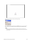
Depending on which browser you are using, a Login hyperlink displays:


