


32 Intel® Blade Server Ethernet Switch Module IXM5414E
The VLAN classification thus associated with received GMRP PDUs establishes the VLAN context
for the received PDU, and identifies the GARP participant instance to which the PDU is directed.
GMRP PDUs transmitted by GMRP participants are VLAN-classified according to the VLAN
context associated with that participant. GMRP Participants in VLAN networking devices apply the
same egress rules that are defined for the transmission port. Therefore:
• GMRP PDUs are transmitted through a given port only if the port is a member of the VLAN
concerned.
• GMRP PDUs are transmitted as VLAN-tagged frames or untagged frames, in accordance with
the state of the Untagged Set for that port for the VLAN concerned. Where VLAN-tagged
frames are transmitted, the VID field of the tag header carries the VLAN Context Identifier
value.
Internet Group Management Protocol (IGMP) snooping
Internet Group Management Protocol (IGMP) snooping is a feature that allows a switch to forward
multicast traffic intelligently on the switch. Multicast IP traffic is traffic destined to a host group.
Host groups are identified by class D IP addresses, which range from 224.0.0.0 to 239.255.255.255.
Based on the IGMP query and report messages, the switch forwards traffic only to the ports that
request the multicast traffic. This prevents the switch from broadcasting the traffic to all ports and
possibly affecting network performance.
Note that the IP address range 224.0.0.1 through 224.0.0.255 is reserved for routing protocols and
other low-level topology discovery or maintenance protocols. For example, the address 224.0.0.1 is
the “all hosts” address, and 224.0.0.2 indicates all routers on this subnet. Also, only the least
significant 23 bits of the IP address are mapped to MAC addresses, so, for example, 225.0.0.123 and
239.128.0.123 and similar IP multicast addresses all map to MAC address 01-00-5E-00-00-7B (for
Ethernet). Therefore, a switch using IGMP Snooping may collapse IP multicast group memberships
into a single Ethernet multicast group.
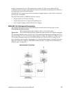
A traditional Ethernet network may be physically separated into different network segments to
prevent overload of the shared media. Bridges and switches connect these segments. When a packet
with a broadcast or multicast destination address is received, the switch will forward a copy into
each of the remaining network segments in accordance with IEEE 802.1D. Eventually, the packet is
made accessible to all nodes connected to the network.
This approach works well for broadcast packets that are intended to be seen or processed by all
connected nodes. In the case of multicast packets, however, this approach can lead to less efficient
use of network bandwidth, particularly when the packet is intended for only a small number of
nodes. Packets will be flooded onto network segments where no node has any interest in receiving
the packet. The problem of wasting bandwidth is even worse when the LAN segment is not shared,
for example in full duplex links.
Allowing switches to snoop IGMP packets is one way to solve this problem. The switch uses the
information in the IGMP packets as they are being forwarded throughout the network to determine
which segments should receive packets directed to particular group addresses.