


Intel® Blade Server Ethernet Switch Module IXM5414E 13
3. Select an I/O module bay in which to install the switch module, in accordance with the
instructions in
“Ethernet interface requirements” on page 9.
4. Remove the filler module from the selected I/O module bay. Store the filler module for future
use.
5. If you have not already done so, touch the static-protective package that contains the switch
module to an unpainted metal part of the SBCE platform for at least two seconds.
6. Remove the switch module from its static-protective package.
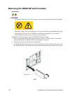
7. Ensure that the release latch on the switch module is in the open position (perpendicular to the
module).
8. Slide the switch module into the appropriate I/O module bay until it stops.
9. Push the release latch on the front of the switch module to the closed position.
10. Make sure that the LEDs on the switch module indicate that it is operating properly. Verify that:
• The DC power LED and the ac power LED on each power module are lit.
• The OK LED on each management module is lit.
• The OK LED on each switch module is lit.
11. If you have other switch modules to install, do so now; otherwise, continue with the next step.
12. Attach any cables required by the switch module. For the location of the connectors on the
SBCE platform, see Intel® Server Chassis SBCE Installation and User’s Guide on the Resource
CD.
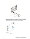
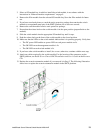
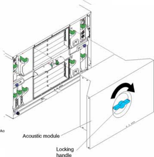
13. Replace the acoustic attenuation module if you removed it in Step 2. The following illustration
shows how to replace the acoustic attenuation module in the SBCE platform.