


17
3 Information Panel LEDs and External Ports
This chapter describes the information panel and LEDs (also known as indicators) on the Intel®
Blade Server Ethernet Switch Module IXM5414E. This chapter also identifies the external ports on
the information panel.
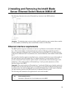
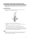
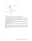
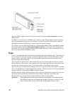
Information panel
The information panel of the IXM5414E switch module consists of LEDs and four external
1000BASE-T ports, as shown in the following illustration.
The Intel® Blade Server Ethernet Switch Module IXM5414E contains:
• Comprehensive LEDs, which display the status of the switch module and the network (see
“LEDs”).
• Fourteen internal ports, one connected to each of the processor blades.
• Two internal full-duplex 10/100 Mbps ports connected to the management module.
• Four external 1000BASE-T Ethernet ports for 10/100/1000 Mbps connections to external
Ethernet devices such as backbones, end stations and servers. These ports are identified as Ext1,
Ext2, Ext3 and Ext4 in the switch configuration menus and are labeled 1 through 4 (from top to
bottom) on the switch module, as shown in the preceding illustration.
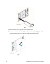
LEDs
The LEDs on the information panel of the IXM5414E switch module include OK, !, Ethernet link,
and Ethernet activity. The following illustration shows the LEDs on the switch module. A
description of each LED follows the illustration.
HHampton -T
Ports
OK
1
2
3
4
TX/RX
TX/RX
TX/RX
TX/RX
LINK
LINK
LINK
LINK
LEDs
LEDs