


Intel® Blade Server Ethernet Switch Module IXM5414E 49
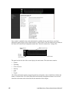
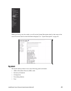
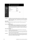
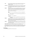
System Description
The product name of this switch.
System Name
The name used to identify this switch. The range for name is from 1 to 31
alphanumeric characters.
System Location
The physical location of this switch. May be up to 31 alphanumeric characters. The
factory default is blank.
System Contact
The person or organization responsible for this switch. May be up to 31
alphanumeric characters. The factory default is blank.
IP Address The IP address of the interface.The factory default value is 10.90.90.9x, where x is
determined by the number of the I/O-module bay into which you have installed the
Ethernet switch module. (See
Table 1.“Default IP addresses based on I/O module
bay numbers” on page 21)
System Object ID
The base object ID for the switch’s enterprise MIB.
System Up Time
The time in days, hours and minutes since the last reboot.
MIBs Supported
The list of MIBs supported by the management agent running on this switch.
Click the Apply button to update the switch with the values on the screen. If you want the switch to
retain the new values across a power cycle you must perform a save.
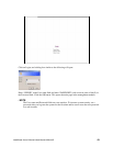
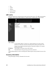
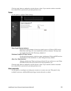
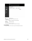
Network connectivity
This panel displays network configuration settings necessary for in-band connectivity. The network
interface is the logical interface used for in-band connectivity with the switch via any of the switch's
front panel ports. The configuration parameters associated with the switch's network interface do not
affect the configuration of the front panel ports through which traffic is switched or routed.
To access the switch over a network, the switch must first be configured with its IP information (IP
address, subnet mask and default gateway).
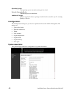
Once you have established in-band connectivity, you can change the IP information using any of the
following:
• Terminal interface via telnet or SSH connections
• SNMP-based management
• Web-based management