Setting the Serial Port Mode
9-12
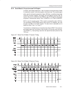
Reception is enabled by configuring SCON0.RBN = 1. Reception of the data
begins at the falling edge of start-bit detection. The RXDx pin is sampled 16
times per bit for any baud rate setting. When the falling edge of the start bit is
detected, the divide-by-16 counter used to generate the receive clock is reset
to align the counter rollover with the bit boundaries. The state of each bit is de-
termined by a majority detect decision on three consecutive samples in the
middle of the bit, providing an amount of noise rejection. At the middle of the
stop bit time, the serial port verifies that the status of SCONx.RI_x = 0 and
SCON0.SM2_x = 1 (if SCON0.SM2_x = 0, the stop bit is a “don’t care”). If these
conditions are true, then the serial port writes the received byte to the SBUFx
register, loads the stop bit into SCONx.RB8_x, and sets the SCONx.RI_x flag.
If the conditions are not met, the data are ignored. After the middle of the stop
bit, the serial waits for another start-bit detection.
Baud rate calculation for mode 3 is identical to that of mode 1, which is fully
explained in section 9.2.2.
Mode 3 has a special provision for multiprocessor communications. This mode
is typically used when a master wants to address a specific slave device on
the bus. The address of the target slave device is transmitted in the first eight
data bits. The ninth bit is used to indicate to the slaves that the data was an
address. If the data matches the slave address, the device can then resume
normal reception. In this mode, nine data bits are received (the ninth bit is
latched into SCON0.RB8). The port can be configured such that when the stop
bit is received, the serial port interrupt will be generated if RB8 = 1. This feature
is enabled by setting bit SCON0.SM2.


