


Code Examples
13-10
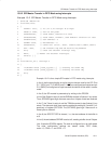
13.8 Code Examples
13.8.1 SPI Master Transfer in Double-Buffer Mode using Interrupt Polling
Example 13−1. SPI Master Transfer in Double-Buffer Mode using Interrupt Polling
1 #include ”MSC1210.H”
2 #include <Stdlib.h>
3 char spi_tx_rx ( char tx_data ) {
4 while((AIE&0x08)!=0x08){ } SPIDATA=tx_data; // Wait until SPItx is set.
5 while((AIE&0x04)!=0x04){ } return(SPIDATA); // Wait until SPIrx is set.
6}
7 void main(void)
8{
9 char j;
10 P1DDRH = 0x75; // P1.7,P1.5,P1.4 = Outputs P1.6 = Input
11 // P1DDRH = 0xDA; // P1.7,P1.5,P1.4 = Inputs P1.6 = Output
12 PDCON &= 0xFE; // Turn on SPI power
13 SPICON=0xF6; // ClkDiv=111(clk/256), DMA=0, Order=0, M/S=1, CPHA=1, CPOL=0
14 // SPICON=0x02; // ClkDiv=Doesnt matter, DMA=0, Order=0, M/S=0, CPHA=1, CPOL=0
15 j=spi_tx_rx(0x78); // Transmit data value=0x78H, Return value is the received data
16 }
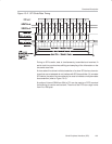
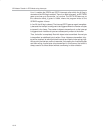
Example 13−1 is for a simple SPI master in double-buffer mode using interrupt
polling. By changing two lines the code can also be used as a slave.
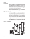
In line 10, the port direction for the pins that are used by the SPI. P1.7( SCLK
pin), P1.5 (MOSI) and P1.4 (SS
) is configured as output, whereas pin P1.6
(MISO) is configured as input, because we are going to use the device as mas-
ter. When configured as a slave, line 10 is commented out and line 11 is un-
commented (line 11 is commented out in Example 13−1).
In line 12, the SPI is powered up by writing to PDCON.
In line 13, the SPICON register is set to put the SPI in master mode, double-
buffer mode, with order = 0, CPHA = 1 and CPOL = 1, and the transfer clock
rate at clk/256. Line 13 must be commented out and line 14 must be uncom-
mented if the device is to be configured for slave-mode operation.
Line 15 calls the subroutine spi_tx_rx. The input to the subroutine is the data
that is to be transmitted and the output is the data that is received.
Line 4 polls AIE[3] ( ESPIT ) to check if the interrupt is on, which indicates that
the transmit buffer is empty. Once the buffer is empty, the next byte can be writ-
ten for transmission.
Line 5 polls AIE[2] (ESPIR) to check if the interrupt is ON, which indicates that
the receive buffer is full. Once this buffer is full, the received byte can be read.
Note:
Some applications require receive-only or transmit-only operation. In these
cases, the subroutine needs to be modified accordingly.