


Bit Addressable SFRs (alphabetical)
F-4
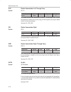
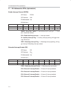
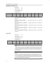
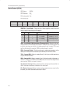
INTERRUPT PRIORITY (IP)
SFR Name: IP
SFR Address: B8
H
Bit−Addressable: Yes
Bit−Definitions:
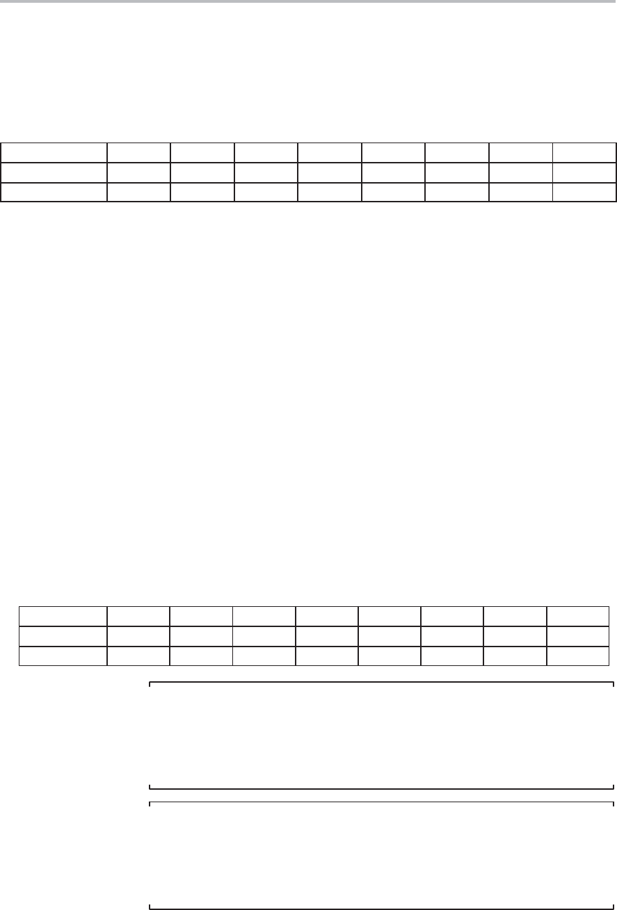
bit 7 bit 6 bit 5 bit 4 bit 3 bit 2 bit 1 bit 0
Name — — PT2 PS PT1 PX1 PT0 PX0
Bit Address BF
H
BE
H
BD
H
BC
H
BB
H
BA
H
B9
H
B8
H
PT2—Priority Timer 2 Interupt. 1 = high-priority interrupt, 0 = low-priority
interrupt.
PS—Priority Serial Interupt. 1 = high-priority interrupt, 0 = low-priority
interrupt.
PT1—Priority Timer 1 Interupt. 1 = high priority interrupt, 0 = low-priority
interrupt.
PX1—Priority External 1 Interupt. 1 = high priority interrupt, 0 = low-priority
interrupt.
PT0—Priority Timer 0 Interupt. 1 = high priority interrupt, 0 = low-priority
interrupt.
PX0—Priority External 0 Interupt. 1 = High priority interrupt, 0 = low-priority
interrupt.
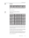
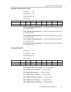
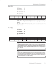
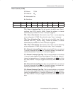
Port 0 (P0)
SFR Name: P0
SFR Address: 80
H
Bit-Addressable: Yes
Bit Definitions:
bit 7 bit 6 bit 5 bit 4 bit 3 bit 2 bit 1 bit 0
Name AD7 AD6 AD5 AD4 AD3 AD2 AD1 AD0
Bit Address 87
H
86
H
85
H
84
H
83
H
82
H
81
H
80
H
Note:
These bit names indicate the function of that I/O line on the P0 bus when
used with external memory (code/RAM). A standard 8052 assembler will not
recognize these bits by the given names; they will only be recognized as
P0.7, P0.6, etc.
Note:
Port 0 is only available for general input/output if the project does not use ex-
ternal code memory or external RAM. When such external memory is used,
Port 0 is used automatically by the microcontroller to address the memory
and read/write data from/to said memory.