Voltage Reference
12-15
Analog-to-Digital Converter
Notice that the speed difference for the synchronized channel changes are
only different by a factor of 3, whereas the non-synchronized channel has a
factor difference of 4.5.
These rates are all based on a reasonable speed for the modulation clock. In
many applications, the mod clock can run as much as 10 times faster. That
would make all of the times for throughput also 10 times faster, as shown in
Table 12−5.
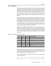
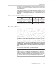
Table 12−5.Output Data Rate and Channel Rate (10x faster)
Filter
Data Rate
(Hz)
Channel Rate
(Hz)
Synchronized
(Hz)
Sinc
3
(dec = 200) 780.125 /4 = 190.53 /3 = 260.04
Sinc
2
(dec = 500) 310.25 /3 = 100.41 /2 = 150.625
Fast Settling (dec = 1800) 80.68 /2 = 40.34 /1 = 80.68
12.12 Voltage Reference
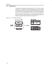
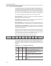
The voltage reference used for the MSC1210 can either be internal or external.
The power-up configuration for the voltage reference is 2.5V internal. The
selection for the voltage reference is made through the ADCON0 register, bits
5 (internal/external selection) and 4 (1.25V/2.5V internal reference voltage).
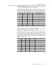
Internal voltage reference is enabled by setting ADCON0.5 (EVREF, SFR ad-
dress:0xDC), which is the default condition. When internal voltage reference is
enabled, it may be selected as either 1.25V or 2.5V depending on the setting of
ADCON0.4 (VREFH). Setting this bit sets the internal reference voltage to 2.5V,
while clearing it sets the internal reference voltage to 1.25V (AVDD = 5V only).
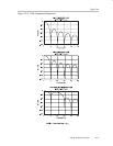
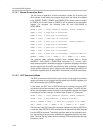
When external voltage is selected, the external voltage reference is differential
and is represented by the voltage difference between pins +VREF and −VREF.
The absolute voltage on either pin (+VREF and −VREF) can range from AGND
to AV
DD
, however, the differential voltage must not exceed 5V. The differential
voltage reference provides an easy means of performing ratiometric measure-
ment.
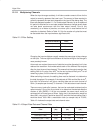
The REFOUT pin should have a 0.1µF capacitor to AGND.
Note:
Enabling the internal V
REF
does not eliminate the need for an external con-
nection. The REFOUT pin must still be connected to VREF+, and VREF−
must still be connected to AGND for normal operation with internal V
REF
. The
only thing that enabling internal V
REF
does is enable the REFOUT pin.


