Description
17-3
Keil Simulator
3) There are also some labeled check boxes whose statuses, checked or
cleared, directly affect the associated bit within the respective bit pattern
of the SFR. A checked status on a check box item represents a logic 1,
while a cleared status on a check box item represents a logic 0. Converse-
ly, the current status of the corresponding bit within the associated bit pat-
tern of the SFR is reflected in the pertinent check box.
4) In addition, there are some non-editable text field windows whose values or
statuses neither represent the value of any SFR nor the status of any particu-
lar bit field within an SFR. Instead, the contents of these text fields represent
the information inferred or deducted from a combination of statuses and con-
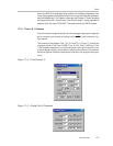
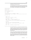
ditions of the pertinent peripheral module(s). For instance, in the snap shot
of the peripheral module depicted in Figure 17−1, Timer/Counter 0, is set for
the timer option and in mode 2. Referring to Chapter 8, Timers, when the
GATE is in an active state, and INT0
is active, if the TR0 bit of the TCON SFR
is also set, the timer continues running, hence, the Run status displayed in
the non-editable text window labeled Status. If the TR0 bit of TCON repre-
sented by the check box is activated once, clearing the state of the TR0 check
box, the state of the non-editable text window labeled Status reverts to Stop,
implying that Timer 0 has stopped running.
Note:
Parameter specification through the various dialog boxes is just an alterna-
tive data entry facility for modifying the content of the corresponding SFR on
the fly, during the debugging process or during the software development
process. This can just as easily be accomplished by modifying the program
so that the software reprograms the pertinent SFR, or by directly accessing
and modifying the internal data address of the corresponding SFR. For
instance, to change the mode selection of the timer/counter 0 module to
mode 3, you could:
1) Assign 0x1B to the variable TMOD in the software program, recompile
the program and re-execute, or
2) Perform a direct memory access to the RAM memory at address location
D:0x89, and overwrite its contents with a value of 0x1B, or
3) Place the cursor on the editable text window labeled TMOD, and replace
its contents with a value of 0x1B.
4) Activate the Mode selection box, and choose the item marked “3: Two
8 Bit Timer/Cnt”.


