Setting the Serial Port Mode
9-5
Serial Communication
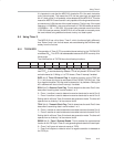
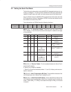
The high four bits (bits 4 through 7) are configuration bits.
The bit REN means receiver enable. This bit is very straightforward; if data need
to be received via the serial port, set this bit. This bit will almost always need to be
set because leaving it cleared will prevent the MSC1210 from receiving serial data.
The function of the SM2 bit depends on the serial mode. In mode 0, the SM2
bit is used to set the baud rate. When SM2 is cleared in this mode, the baud
rate is f
OS
/12. When SM2 is set in this mode, the baud rate is f
OSC
/4. In mode
3, the SM2 bit is a flag for multiprocessor communication. Generally, whenever
a byte has been received, the MSC1210 will set the RI flag. This lets the
program know that a byte has been received and that it needs to be processed.
However, when SM2 is set, the RI flag will only be triggered if the ninth bit
received is a 1. That is to say, if SM2 is set and a byte is received whose ninth
bit is clear, the RI flag will never be set. This can be useful in certain advanced
serial applications that allow multiple MSC1210s (or other hardware) to
communicate amongst themselves. For now, it is safe to say that this bit should
almost always be clear so that the flag is set upon reception of any character.
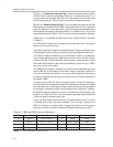
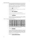
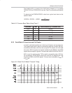
Bits SM0 and SM1 let the serial mode be set to a value between 0 and 3,
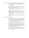
inclusive. The four modes are defined in Table 9−1. As shown, selecting the
serial mode selects the mode of operation (8-bit/9-bit, UART, or shift register)
and also determines how the baud rate will be calculated.
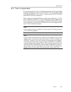
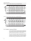
9.2.1 Serial Mode 0: Synchronous Half-Duplex
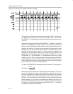
In mode 0, serial data transfers are eight bits long, half-duplex, and synchro-
nous. The serial data are transmitted and received through the RXD pin. The
shift clock is generated on the TXD pin. Eight bits are transmitted or received
on each data transfer, LSB first. The data transmission begins when data are
written to SBUF.
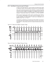
Data reception begins when the REN_0/REN_1 bit is set and the RI_0/RI_1
bit is cleared in the corresponding SCON SFR. The shift clock is activated and
the UART shifts data in on each rising edge of the shift clock until eight bits
have been received. One instruction cycle after the eighth bit is shifted in, the
RI_0/RI_1 bit is set, and reception stops until the software clears the RI bit. The
baud rate is either f
OSC
/12 (if SCONx.5 is clear) or f
OSC
/4 (if SCONx.5 is set).
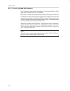
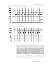
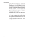
RXD is used for serial TX and RX of data, LSB first. TXD is used as the baud
clock. Transmission is initiated by any instruction that writes to SBUF.


