


Timers
17-5
Keil Simulator
Due to the MSC1210 peripherals being modular and relatively independent, even
if they share registers, each peripheral has it own unique set of bits that are associ-
ated and affiliated with it. For instance, referring to the Chapter 8, Timers, the status
and setup bits for both Timer/Counter 0 and Timer/Counter 1 occupy separate bit
positions within the same TCON SFR. The same holds for the TMOD register.
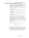
17.2.1 Timer 0 & 1 Example
Due to this sample program setting the interrupt trigger edge type for edge trig-
ger, a transition from cleared to checked on the INT0
line will induce an inter-
rupt request.
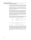
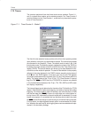
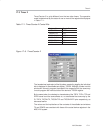
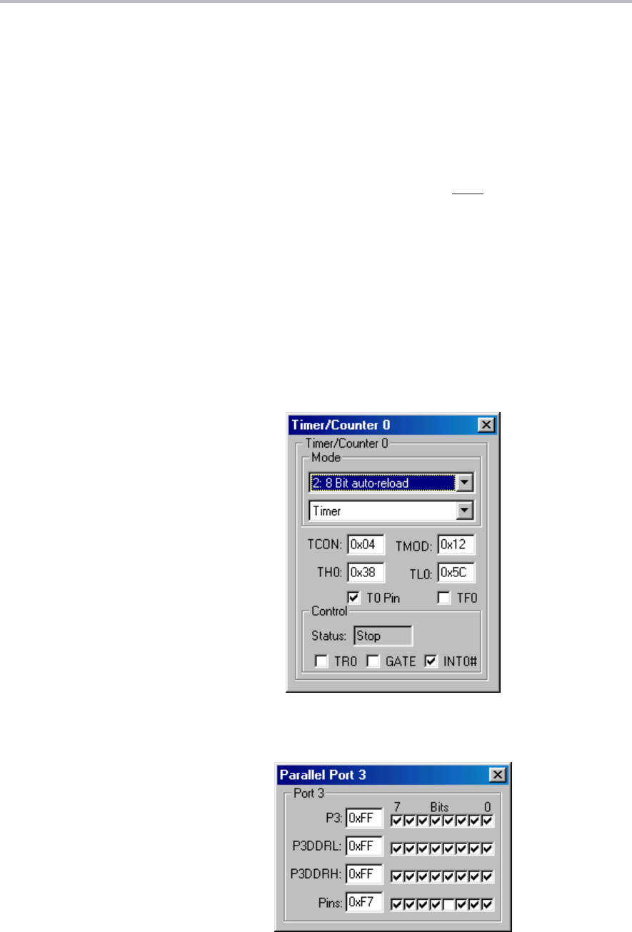
The contents of the registers TH0, TL0, TH1 and TL1 in Figure 17−2 reflect the
snapshot values of the Timer 0 MSB, Timer 0 LSB, Timer 1 MSB and Timer
1 LSB registers respectively. As explained earlier, altering the contents of any
of these register displays is equivalent to altering the contents of the associat-
ed device register outside the operational confines of the program being exe-
cuted.
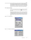
Figure 17−2. Timer/Counter 0
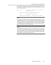
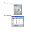
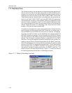
Figure 17−3. Parallel Port 3 Peripheral