Calibration
12-11
Analog-to-Digital Converter
12.10 Calibration
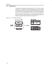
The offset and gain errors in the MSC1210 ADC, or a complete measurement
system, can be reduced with calibration. The calibration mode control bits in
the ADCON1 register (SFR address: 0xDD) can select 5 different calibration
processes. These include: internal (self) calibration of offset, gain, or both, and
system calibration of offset or gain. Each calibration process takes seven t
DATA
periods to complete. Therefore, it takes 14 t
DATA
periods to complete self cal-
ibration of both offset and gain, which is represented by one mode control bit
selection.
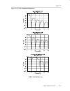
For system calibration, the appropriate signal must be applied to the inputs.
The system calibration offset mode requires a zero differential input signal. It
then computes an offset that will nullify the offset in the system. The system
calibration gain mode requires a positive full-scale differential input signal. It
then computes a value to nullify gain errors in the system. For example, in a
weigh-scale application, the use of the system offset calibration could be used
to null the system for a tare weight. Then the measurements that follow would
only have the new weight in the output of the ADC.
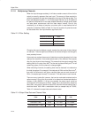
Calibration should be performed after power on, a change in temperature, or
a change of the PGA. For operation with a reference voltage greater than
(AV
DD
− 1.5V), the buffer must also be turned off during calibration. Calibration
will remove the effects of the ODAC, therefore, changes to the ODAC register
must be done after calibration, otherwise the calibration will remove the effects
of the offset.
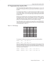
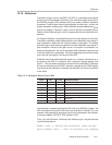
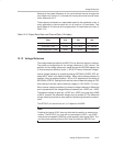
Table 12−2.Calibration Mode Control Bits
CAL2 CAL1 CAL0 Calibration Mode
0 0 0 No calibration (default)
0 0 1 Self calibration, offset and gain
0 1 0 Self calibration, offset only
0 1 1 Self calibration, gain only
1 0 0 System calibration, offset only
1 0 1 System calibration, gain only
1 1 0 Reserved
1 1 1 Reserved
The calibration is started by setting the CALx bits in the ADCON1 register. The
ADC conversion interrupt will occur when the calibration is finished. If it is not
masked, it will generate an interrupt or the bit can be monitored in the Peripher-
al Interrupt register (AISTAT.5, SFR address: 0xA7).
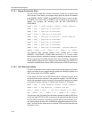
Thus, a full self-calibration, calibrating both offset and gain, may be executed
in the following fashion:
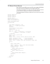
ADCON1 = 0x01; // Initiate self−calibration, offset and gain
while(!(AISTAT & 0x20)); // Wait for interrupt to be triggered


