Types of Interrupts
10-12
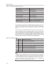
Table 10−8.Clearing Auxiliary Interrupts
Aux Interrupt Type Method to Clear Interrupt
Seconds interrupt Read SECINT SFR
Summation interrupt Read SUMR0 SFR
ADC conversion interrupt Read ADRESL SFR
Millisecond interrupt Read MSINT SFR
SPI transmit interrupt Write SPIDATA SFR
SPI receive interrupt Read SPIDATA SFR
Analog low-voltage interrupt Remove low-voltage condition
Digital low-voltage interrupt Remove low-voltage condition
Breakpoint interrupt Set BP = 1, bit 7 of BPCON SFR
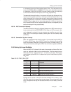
To enable Auxiliary interrupts, the EICON.5 (EAI) bit must be set, which en-
ables auxiliary interrupts. When so configured, the MSC1210 will be config-
ured to respond to those auxiliary interrupts that are enabled in the AIE (A6
H
)
SFR.
The Auxiliary Interrupt Enable (AIE) SFR controls which of the auxiliary inter-
rupts are enabled and which are disabled (masked). If auxiliary interrupts are
enabled, as described in the previous paragraph, and the specific auxiliary in-
terrupt is enabled in AIE, that condition will set the EICON.4 (AI) flag to indicate
an auxiliary interrupt and vector through 0033
H
. The ISR must clear the AI flag
before returning, or the auxiliary interrupt will be triggered again.
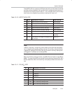
Table 10−9.AIE (A6
H
) SFR
Bit Name Explanation of Function
7 ESEC Enable Seconds Auxiliary Interrupt
6 ESUM Enable Summation Auxiliary Interrupt
5 EADC Enable ADC Conversion Auxiliary Interrupt
4 EMSEC Enable Millisecond Auxiliary Interrupt
3 ESPIT Enable SPI Transmit Auxiliary Interrupt
2 ESPIR Enable SPI Receive Auxiliary Interrupt
1 EALV Enable Analog Low-Voltage Auxiliary Interrupt
0 EDLVB Enable Digital Low-Voltage or Breakpoint Auxiliary Interrupt
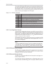
Note:
Reading from the AIE SFR will return the current state of the corresponding
condition, regardless of whether or not an interrupt is enabled. For example,
if an ADC conversion has been completed and an interrupt would be trig-
gered if it were enabled, reading the EADC bit will return a 1, regardless of
whether or not the interrupt was actually enabled.


