


Timer 2
17-11
Keil Simulator
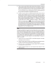
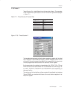
17.3 Timer 2
Timer/Counter 2 is quite different from the two other timers. The operation
mode is determined by the status of one or more of the register bits displayed
in Table 17−1.
Table 17−1.Timer/Counter 2 Control Bits
Register Bit Toggle Box Name
T2CON.TR2 TR2
T2CON.C/T2 TC/T
T2CON.CP/RL2 CP/RL2
T2CON.EXEN2 EXEN2
T2CON.TCLK TCLK
T2CON.RCLK RCLK
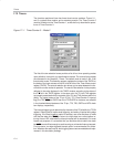
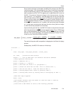
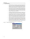
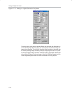
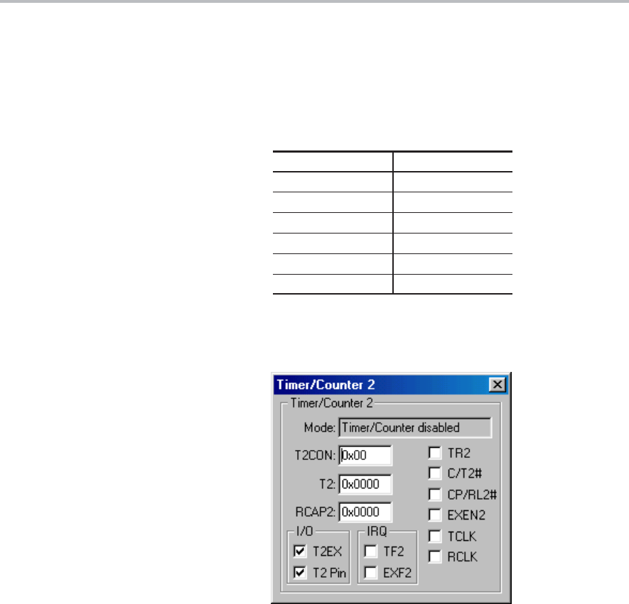
Figure 17−6. Timer/Counter 2
The hexadecimal equivalent of the bit pattern created by toggling the individual
bits is displayed in the editable text display, T2CON. Writing a number into this
window will correctly program the states of the respective bit; the same way
it would program the individual bits of the device’s T2CON register.
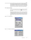
By the same token, the checked or cleared state of the T2EX, T2 Pin, TF2 and
EXF2 boxes have the same effects on, or are affected the same way by the
P1.T2EX, T2CON.T2, T2CON.TF2 and T2CON.EXF2 pins respectively, as
discussed earlier.
The values and the implications of the contents of the editable text windows
T2 and RCAP2 are consistent with those of the actual device registers in the
MSC1210 system.