


SFR Definitions
3-5
Special Function Registers (SFRs)
3.5 SFR Definitions
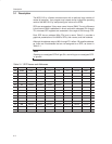
This section will endeavor to quickly overview each of the SFRs found in the
SFR chart map of Table 3−1. It is not the intention of this section to fully explain
the functionality of each SFR—this information will be covered in separate
chapters. This section is to just give a general idea of what each SFR does.
P0 (Port 0, Address 80
H
, Bit-Addressable): This is input/output port 0. Each
bit of this SFR corresponds to one of the pins on the microcontroller. For exam-
ple, bit 0 of port 0 is pin P0.0, bit 7 is pin P0.7. Writing a value of 1 to a bit of
this SFR sets a high level on the corresponding I/O pin, whereas a value of 0
brings it to a low level.
Note:
Even though the MSC1210 has four I/O ports (P0, P1, P2, and P3), if the
hardware uses external RAM or external code memory (i.e., if the program
is stored in an external ROM or EPROM chip, or if external RAM chips are
being used), P0 or P2 may not be used. This is because the MSC1210 uses
ports P0 and P2 to address the external memory (refer to Section 15.1 for
the detailed control of the port usages). Thus, if external RAM or code
memory is being used, only ports P1 and P3 (except P3.6 and P3.7) may be
used by the application.
SP (Stack Pointer, Address 81
H
): This is the stack pointer of the
microcontroller. This SFR indicates where the next value to be taken from the
stack will be read from Internal RAM. If a value is pushed onto the stack, the
value will be written to the address of SP + 1. That is to say, if SP holds the value
07
H
, a PUSH instruction will push the value onto the stack at address 08
H
. This
SFR is modified by all instructions that modify the stack, such as PUSH, POP,
LCALL, RET, RETI, and whenever interrupts are triggered by the
microcontroller.
Note:
The SP SFR, on startup, is initialized to 07
H
. This means the stack will start at
08
H
and will grow to larger addresses of internal RAM. It is necessary to initialize
SP in the program to some other value if alternate register banks and/or bit me-
morywill be used because alternate register banks 1, 2, and 3, as well as the
user bit variables, occupy internal RAM from addresses 08
H
through 2F
H
. It is
not a bad idea to initialize SP to 2F
H
as the first instruction of every one of the
programs, unless there is complete confidence that the program will not be us-
ing register banks and bit variables.