


Setting the Serial Port Mode
9-4
TI_0 (bit 1)—Transmitter Interrupt Flag. This bit indicates that data in the Se-
rial Port 0 buffer has been completely shifted out. In serial port mode 0, TI_0
is set at the end of the eighth data bit. In all other modes, this bit is set at the
end of the last data bit. This bit must be manually cleared by software.
RI_0 (bit 0)—Receiver Interrupt Flag. This bit indicates that a byte of data has
been received in the Serial Port 0 buffer. In serial port mode 0, RI_0 is set at the
end of the eighth bit. In serial port mode 1, RI_0 is set after the last sample of the
incoming stop bit subject to the state of SM2_0. In modes 2 and 3, RI_0 is set
after the last sample of RB8_0. This bit must be manually cleared by software.
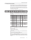
Additionally, it is necessary to define the function of SM0 and SM1, as shown
in Table 9−1.
The SCON0 SFR allows us to configure the primary serial port. Go through
each bit and review its function.
The low four bits (bits 0 through 3) are operational bits. They are used when actu-
ally sending and receiving data; they are not used to configure the serial port.
The TB8 bit is used in modes 2 and 3, which transmit a total of nine data bits.
The first eight data bits are the eight bits of the main value, and the ninth bit
is taken from TB8. If TB8 is set and a value is written to the serial port, the bits
of the data will be written to the serial line followed by a set ninth bit. If TB8 is
clear, the ninth bit will be clear.
The RB8 bit also operates in modes 2 and 3 and functions essentially the same
way as TB8, but on the reception side. When a byte is received in modes 2 or
3, a total of nine bits are received. In this case, the first eight bits received are
the data of the serial byte received, and the value of the ninth bit received will
be placed in RB8.
TI means transmit interrupt. When a program writes a value to the serial port,
a certain amount of time passes before the individual bits of the byte are shifted
out of the serial port. If the program writes another byte to the serial port before
the first byte is completely output, the data being sent is intertwined. Therefore,
the MSC1210 lets the program know that it has shifted out the last byte by set-
ting the TI bit. When the TI bit is set, the program assumes that the serial port
is free and ready to send the next byte.
Finally, the RI bit means receive interrupt. It functions similarly to the TI bit, but
it indicates that a byte has been received. That is to say, whenever the
MSC1210 receives a complete byte, it triggers the RI bit to let the program
know that it needs to read the value quickly, before another byte is read.
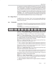
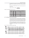
Table 9−1.SM0 and SM1 Function Definitions.
MODE Sync/Async Baud Clock Data Bits Start/Stop Ninth-Bit Function
0 Sync clk/4 or clk/12 8 None None
1 Async Timer 1 or Timer 2
(1)
8 1 Start, 1 Stop None
2 Async clk/32 or clk/64 9 1 Start, 1 Stop 0, 1, Parity
3 Async Timer 1 or Timer 2
(1)
9 1 Start, 1 Stop 0, 1, Parity
Notes: 1) Timer 2 available for Serial Port 0 only.