PWM Generator
11-8
11.3.1 Example of PWM Tone Generation
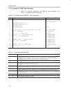
Table 11−2 illustrates configuring the PWM for tone generation, and
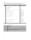
Table 11−3 explains selected statements.
Table 11−2.Configuring the PWM for Tone Generation
Stmt ‘C’ Source Code Assembly Source Code
1 // PWM PUBLIC main
RSEG ???main?PWM
2 #include <reg1210.h>
3 #define OneUsConst (2−1)
4 sbit p33=p3^3;
5 void main(void) Main:
6{
7 PDCON &= 0xED; // turn on tone gen & sys timer ANL PDCON,#0Edh
8 USEC = OneUsConst; MOV USEC,#01h
9 P33 = 1; // turn on P3.3 SETB p33
10 PWMCON = 0; // select PWMPeriod MOV PWMCON,#00h
11 PWM = 5; // Set PWMPeriod MOV PWMHI,#00h
MOV PWMLOW,#05h
12 PWMCON = 0x10; // select PWMDuty MOV PWMCON,#10h
13 PWM = 4; // Set PWMDuty MOV PWMHI,#00h
MOV PWMLOW,#04h
14 PWMCON = 0x09; // Enable PWM MOV PWMCON,#09h
15 While(1) {} SJMP $
16 }
Table 11−3.Statement Explanations
Statement # Explanation
7 ANDing PDCON with ED
H
effectively turns off bits 1 (PDST) and 4 (PDPWM). Clearing the
PDST (Power Down System Timer) bit turns the system timer on, while clearing the
PDPWM (Power Down PWM module) bit turns the PWM module on.
8 Sets the USEC SFR to define 1µs, which will be used for determining the PWM timing.
9 P3.3 must be set to 1 prior to using PWM or tone generator. If P3.3 is clear, the PWM or
tone generator will not produce any output.
10 Clearing bit 4 by setting PWMCON to 0 selects the PWM Period register, which will be
written to in the next statement.
11 Having selected PWM Period in statement 10, this statement sets the PWM Period to 5.
12 Setting bit 4 by setting PWMCON to 10
H
select the PWM Duty register will be written to in
the next statement.
13 Having selected PWM Duty in statement 12, this statement sets the PWM Duty to 4.
14 This statements enables the PWM.


