


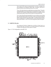
MSC1210 Pin-Out
1-6
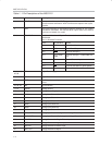
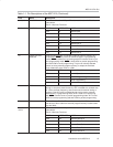
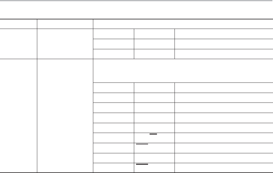
Table 1−1 Pin Descriptions of the MSC1210 (Continued)
Pin # Name Description
46, 47,
49-54
P0.0−P0.7 P0.5 AD5 Address/Data Bit 5
49-54
P0.6 AD6 Address/Data Bit 6
P0.7 AD7 Address/Data Bit 7
55, 56,
59−64
P1.0−P1.7 Port 1 is a bidirectional I/O port. The alternate functions for Port 1 are
listed below.
Port 1—Alternate Functions:
PORT ALTERNATE MODE
P1.0 T2 T2 Input
P1.1 T2EX T2 External Input
P1.2 RxD1 Serial Port Input
P1.3 TxD1 Serial Port Output
P1.4 INT2/SS External Interrupt/Slave Select
P1.5 INT3/MOSI External Interrupt/Master Out−Slave In
P1.6 INT4/MISO External Interrupt/Master In−Slave Out
P1.7 INT5/SCK External Interrupt/Serial Clock
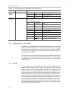
1.2.1 I/O Ports (P0, P1, P2, and P3)
Of the 64 pins on the MSC1210, 32 of them are dedicated to I/O lines that have
a one-to-one relation with SFRs P0, P1, P2, and P3. The developer may raise
and lower these lines by writing 1s or 0s to the corresponding bits in the SFRs.
Likewise, the current state of these lines may be found by reading the corre-
sponding bits of the SFRs.
All of the ports have optional pull-up resistors that are enabled when the port
is in 8051 mode, as configured by the PxDDRL/H SFRs. The pull-up resistors
are disabled when the port is configured in any other mode, or when accessing
external memory.
1.2.1.1 Port 0
Port 0 is dual-function: in some designs port 0 I/O lines are available to the de-
veloper to access external devices, while in other designs it is used to access
external memory. If the circuit requires external RAM, the microcontroller will
use port 0 to latch in/out the 8-bit data word, as well as the low eight bits of the
address in response to a MOVX instruction, as long as the hardware configu-
ration registers are set up correctly. Port 0 I/O lines may be used for other func-
tions as long as external data memory is not being accessed at the same time
and the hardware configuration registers are set up correctly. If the circuit re-
quires external code memory, the microcontroller will use port 0 I/O lines to ac-
cess each instruction to be executed. In this case, port 0 cannot be used for
other purposes, because the state of the I/O lines are constantly being modi-
fied to access external code memory.