


Low-Voltage Detect
14-3
Additional MSC1210 Hardware
The detect circuit must activate whenever the supply voltage drops below the
programmed level. In order to account for temperature and process variations,
the trip levels are typically higher than the specified value, to provide some
margin. For example, when 4.5V is selected, the detect output will typically ac-
tivate when the supply drops below 4.7V.
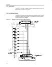
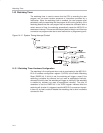
14.2.1 Power Supply
V
SPD
powers the digital section resistor string and the comparators. V
SPA
powers the analog section resistor string and the bandgap voltage. Level
shifters, where needed, are included inside the block.
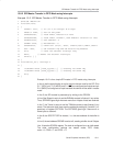
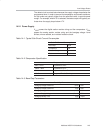
Table 14−1.Typical Sub-Circuit Current Consumption
Sub−Ckt Current Consumption
Band Gap 20µA
Compartors 2µA
Resistor String 6µA
Total 40µA
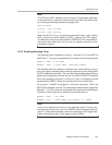
Table 14−2.Comparator Specification
Comparator Parameters
50mV ± 2mV Hysteresis at 2.5V
100mV ± 8mV Hysteresis at 4.7V
26mV Hysteresis at Each Terminal
400nS Response Time for Slow Input
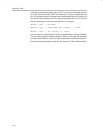
Table 14−3.Band Gap Parameters
Band Gap Parameters
Bandgap Voltage Reference (min) 1.00V
Bandgap Voltage Reference (typ) 1.22V
Bandgap Voltage Reference (max) 1.50V
Minimum Supply Voltage (V
SPA
) 1.50V
Bandgap Startup Time (typ) < 16µS