Internal RAM
2-9
MSC1210 Memory Organization
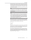
As shown, bit memory is not really a new type of memory, it is just a subset of
internal RAM. However, because the MSC1210 provides special instructions
to access these 16 bytes of memory on a bit-by-bit basis, it is useful to think
of it as a separate type of memory. Always keep in mind that it is just a subset
of internal RAM, and that operations performed on internal RAM can change
the values of the bit variables.
Note:
If your program does not use bit variables, you may use internal RAM locations
20
H
through 2F
H
for your own use. When using bit variables, be very careful
about using addresses from 20
H
through 2F
H
, as you may end up overwriting
the value of your bits.
Note:
By default, the MSC1210 initializes SP to 07
H
when the microcontroller is
booted. This means that the stack will start at address 08
H
and expand up-
wards. If using the alternate register banks (banks 1, 2 or 3), SP must be initial-
ized to an address above the highest register bank being used. Otherwise the
stack will overwrite the alternate register banks. Similarly, if using bit variables,
it is usually a good idea to initialize SP to some value greater than 2F
H
to ensure
that the bit variables are protected from the stack.
Bit memory 00
H
through 7F
H
is for user-defined functions in their programs.
Bit memory 80
H
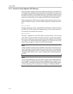
and above are used to access certain SFRs (see section
2.4.4) on a bit-by-bit basis. For example, if output lines P0.0 through P0.7 are
all clear (0), to turn on the P0.0 output line, either execute:
MOV P0,#01h
or execute:
SETB 80h
Both these instructions accomplish the same thing. However, using the SETB
command will turn on the P0.0 line without affecting the status of any of the
other P0 output lines. The MOV command effectively turns off all the other out-
put lines that, in some cases, may not be acceptable.
When dealing with bit addresses of 80
H
and above, remember that the bits re-
fer to the bits of corresponding SFRs that are divisible by eight. This is a com-
plicated way of saying that bits 80
H
through 87
H
refer to bits 0 through 7 of SFR
80
H
, bits 88
H
through 8F
H
refer to bits 0 through 7 of SFR 88
H
, bits 90
H
through
97
H
refer to bits 0 through 7 of 90
H
, etc.


