


Using Timers to Measure Time
8-6
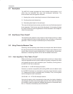
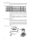
As is shown in the previous chart, four bits (two for each timer) are used to
specify a mode of operation. The modes of operation are shown in Table 8−2.
Table 8−2.Timer Modes and Usage
TxM1 TxM0 Timer
Mode
Description of Timer Mode Timer 1 Timer 0
0 0 0 13-bit timer/counter Y Y
0 1 1 16-bit timer/counter Y Y
1 0 2 8-bit timer/counter with auto-reload Y Y
1 1 3 Two 8-bit counters (split timer mode) N Y
The TMOD.GATE bit controls gating of the timer/counter. If TMOD.GATE is
cleared, the timer/counter increments only if TCON.TRx is set. If TMOD.GATE
is set, the timer/counter increments only if TCON.TRx is set and the corre-
sponding INTx pin is held high. This feature can be used for pulse width mea-
surements.
The TMOD.CT
bit selects counter or timer operation. If TMOD.CT is cleared,
the timer/counter register is incremented on either f
osc
/4 or f
osc
/12 (based on
the state of CKCON.TxM ). If TMOD.CT
is set, the timer/counter register is in-
cremented by the Tx pin.
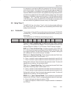
8.3.3.1 13-Bit Time Mode (mode 0)
Timer mode 0 is a 13-bit timer. This is a relic that was kept around in the 8052
(and subsequently MSC1210) to maintain compatibility with its predecessor,
the 8048. The 13-bit timer mode is not normally used in new development.
In this mode, the timer/counter uses five bits of the TLx register and all eight
bits of the THx register for the 13-bit register. Therefore, the upper three bits
of TLx must be masked if they are used by software. When the timer/counter
rolls over on a transition from 01FFF
H
, the timer/counter interrupt flag is set
(TCON.TFx).
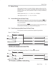
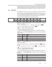
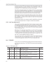
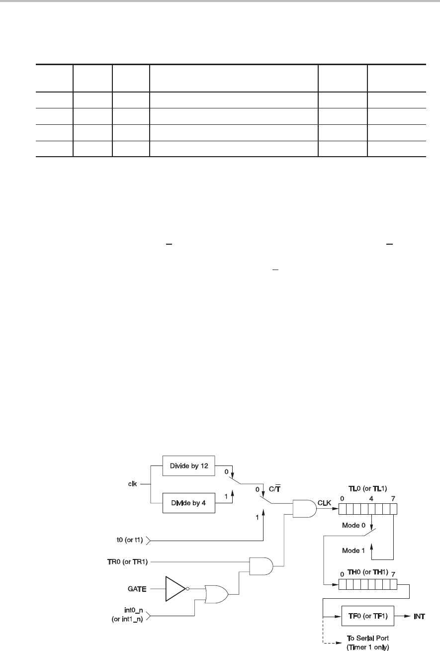
Figure 8−1. Timer 0/1 Block Diagram for Modes 0 and 1