SFR Definitions
3-13
Special Function Registers (SFRs)
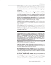
FTCON (Flash Memory Timing Control, Address EF
H
): This SFR controls
the timing and period of flash memory, specifically for writing and erasing flash
memory. The period of writing to flash memeory is determined by USEC and
the low four bits of FTCON, and should produce a write period of 30µs to 40µs.
Meanwhile, the period of erasing flash memory is determined by
MSECH/MSECL and the high four bits of FTCON, and should produce an
erase period of 4ms to 11ms.
B (B Register, Address F0
H
, Bit-Addressable): The B register is used in two
instructions: multiply and divide. The B register is also commonly used by pro-
grammers as an auxiliary register to store temporary values.
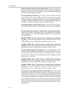
PDCON (Power-Down Control, Address F1
H
): This SFR allows the user
program to power down specific on-chip peripherals that the program may not
need at a given moment, thus contributing to a more energy-efficient design.
This SFR allows the user to power down (or power up) the PWM generator,
ADC, watchdog, SPI system, and the system timer.
PASEL (PSEN
/ALE select, Address F2
H
): This SFR allows for a user pro-
gram that runs entirely in internal flash memory to control the ALE and PSEN
lines. The PASEL allows you to configure both ALE and PSEN such that they
either behave normally or may be forced high or low. In this manner, PSEN and
ALE may be used as two additional output lines if they are not needed for their
normal functions.
Note:
When these two lines are used as output lines, they should only drive light
capacitive loads to avoid triggering serial or parallel flash programming
modes.
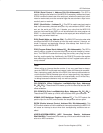
ACLK (Analog Clock, Address F6
H
): This SFR is used to determine the ana-
log clock for the ADC. The value of ACLK, plus 1, multiplied by 64 represents
the number of instruction cycles between each analog sample. For example,
if an instruction cycle lasts 100ns and ACLK is 9, then ACLK + 1 = 10, so
10 S 100ns = 1µs, multiplied by 64 would result in a sample being made every
64µs. A sample every 64µs is equivalent to 1 000 000 / 64 = 15 625 samples
per second.
SRST (System Reset Register, Address F7
H
): Setting this SFR to 1 and then
0 will cause a system reset to occur. This provides an easy way to reset the
system via software without the need for external circuitry.
EIP (Extended Interrupt Priority, Address F8
H
): This is the pnterrupt priority
register for the extended interrupts that are enabled/disabled using the EIE
SFR (E8
H
).
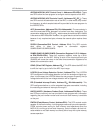
SECINT (Seconds Timer Interrupt, Address F9
H
): This SFR can be set to
cause an interrupt to occur after the specified number of fractions of a second.
Specifically, this SFR can cause an interrupt every 100 milliseconds to every
12.8 seconds, assuming the HMSEC is set to a value that represents 100ms.
The precise frequency at which SECINT will cause an interrupt depends on
the system clock and the values of the MSECH, MSECL, HMSEC, and
SECINT SFRs.


