


mVision 2 Debug Program Example
17-39
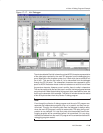
Keil Simulator
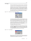
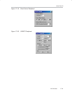
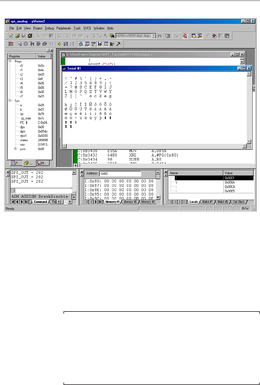
Figure 17−17. Keil Debugger
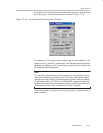
The window labeled Serial #1 shows the printed ASCII character representation
of the data bytes received by the main SPI program from the debugging pro-
gram. Note that the first character printer is an ! mark which has a numerical val-
ue of 0x21. This was the first value of j to be transmitted from the debugger
through the SPI_IN portal. The subsequent characters are supposed to corre-
spond to ASCII characters whose numerical values are a value of one off from
the previous character. However, once in a while, there is a skip in characters.
This can be explained by the fact that once in a while, the two programs become
unsynchronized. Better twatch delay timing would have resolved this issue, but
that is not the essence of this example. The Serial #1 window shows the results
of two 50-byte transfers from the µVersion 2 debug program.
Note:
Even though the µVersion 2 debug program and the main SPI program are
separate and independent programs, they run in parallel, and they are syn-
chronized. This way, the incoming data from the debugger is always ready
when the main SPI program is ready to receive data. The delay timing com-
putation is very delicate. If it is too short, data to be transmitted from the de-
bugging program will be overwritten before it is transmitted. If it is too long,
the data transmitted from the main SPI program will be overwritten before the
debugging program reads it.