Hardware Configuration
15-4
15.1.1.2 Hardware Configuration Register 1 (HCR1)
Hardware configuration register 1 (HCR1) is used primarily to configure the
brownout detection for both the digital and analog power supplies. It is also
used to configure whether ports 0, 2, and 3 are used as general I/O ports, or
take part in external memory access.
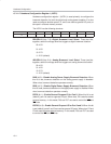
The HCR1 has the following structure:
bit 7 bit 6 bit 5 bit 4 bit 3 bit 2 bit 1 bit 0
CADDR 7E
H
DBLSEL1 DBLSEL0 ABLSEL1 ABLSEL0 DAB DDB EGP0 EGP23
DBLSEL1/0 (bits 7-6)—Digital Brownout Level Select. These two bits,
together, select the voltage level that triggers a digital brownout situation.
00: 4.5V
01: 4.2V
10: 2.7V
11: 2.5V (default)
ABLSEL1/0 (bits 5-4)—Analog Brownout Level Select. These two bits,
together, select the voltage level that triggers an analog brownout situation.
00: 4.5V
01: 4.2V
10: 2.7V
11: 2.5V (default)
DAB (bit 3)—Disable Analog Power−Supply Brownout Detection. When
this bit is set, brownout detection on the analog power supply is disabled.
When clear, brownout detection operates normally.
DDB (bit 2)—Disable Digital Power−Supply Brownout Detection. When
this bit is set, brownout detection on the digital power supply is disabled. When
clear, brownout detection operates normally.
EGP0 (bit 1)—Enable General-Purpose I/O for Port 0. When this bit is set
(default), port 0 is used as a general I/O port. When clear, P0 is used to access
external memory—in this mode, P3.6 and P3.7 are used to control the WR
and
RD
lines.
EGP23 (bit 0)—Enable General-Purpose I/O for Port 2 and 3. When this bit
is set (default), ports 2 and 3 sre used as general I/O ports. When clear, P2 and
P3 are used to access external memory—in this mode, P3.6 and P3.7 are used
to control the WR
and RD lines.


