


Input Buffer
12-8
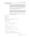
The previous code detects either an open- or short-circuit situation based on
the ADC sample. Also note that the comparison is less than 0.01, due to the
fact that the ADC generally will not return exactly 0.
12.5 Input Buffer
The input buffer reduces the likelihood of an offset in the measurements taken
by the ADC. It should be used whenever the characteristics of the input signal
allow. Essentially, the only time the input buffer should not be used is if the max-
imum voltage on either analog input is more than 1.5V below the positive rail
voltage.
The input impedance of the MSC1210 without the buffer is 5MΩ/PGA.
With the
buffer enabled, the impedance is typically 10GΩ, the input voltage range is re-
duced, and the analog power-supply current is higher. The buffer is controlled
by the BUF bit in the ADC control register (ADCON0.3); setting BUF enables
the input buffer, while clearing it disables the input buffer.
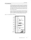
12.6 Analog Input
When the buffer is not selected, the input impedance of the analog input
changes with clock frequency (ACLK F6H) and gain (PGA). The relationship
is:
A
IN
Impedance(W) +
ǒ
1 @ 10
6
ACLKFrequency
Ǔ
@
ǒ
5 @ 10
6
PGA
Ǔ
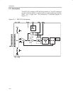
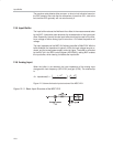
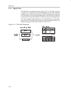
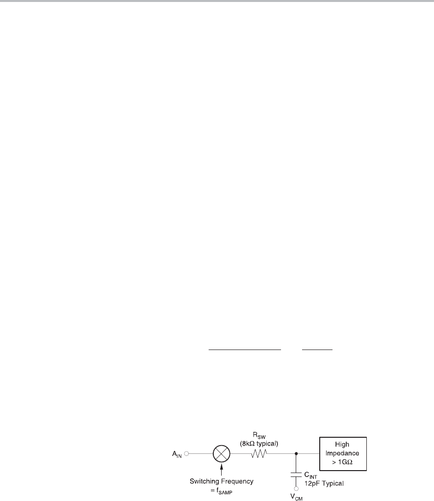
Figure 12−3 shows the basic input structure of the MSC1210.
Figure 12−3. Basic Input Structure of the MSC1210