Watchdog Timer
17-12
17.4 Watchdog Timer
The process of setting, and the operation of the watchdog timer peripheral fa-
cility are similar to those of the other peripherals we have considered so far.
However, this module has an additional feature: the special access setting or
resetting of the status conditions of the EWDT, DWDT, RWDT check boxes.
These boxes directly or indirectly affect, or are affected by, the status and con-
ditions of the EWDT, DWDT, RWDT bits of the WDTCON SFR respectively.
Just as these bits, for security, require special access of an application of a se-
quence of a logic 1, followed by a logic 0 for their respective setting and reset-
ting in the actual MSC1210 device, so do the check boxes in this simulator pe-
ripheral. Please see section 14.3, Watchdog Timer, of this manual for the de-
scription of the special access programming.
To enable the watchdog timer system, the watchdog timer must be turned on
either by placing a check mark on the PDWDT check box, or writing a logic 1
into the PDWDT bit of the PDCON SFR from within the software. The appropri-
ate value must also be written into the watchdog timer register through the
WDTIMER editable text window. This would properly set the WDCNT counter
bits (lower five bits) of WDTIMER, through which watchdog expiration time is
defined. Then the special accessed procedure is performed for the EWDT
check box, involving the sequential process of activating the box marked 1 fol-
lowed by the box marked 0 that are associated with the EWDT check box.
While the watchdog timer is running, performing repeating the special access
process for the DWDT will disable the watchdog timer. This will automatically
clear the check mark in the EWDT check box. On the other hand, you could
also perform the special access procedure on the RWDT check box. This
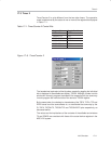
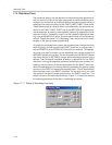
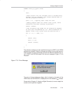
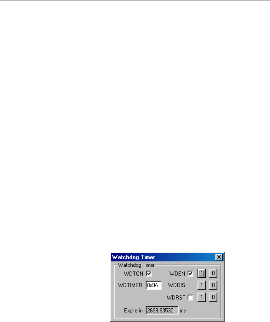
places a check on the associated check box. Figure 17−7 shows the status of
the watchdog peripheral mid-stride of a watchdog countdown.
Figure 17−7. Status of Watchdog Peripheral


