SFR Definitions
3-10
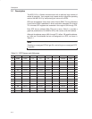
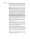
AISTAT (Auxiliary Interrupt Status, Address A7
H
): This is a read-only SFR
that will provide you with the current status of all the enabled (not masked by
AIE) auxiliary interrupts. Those interrupts that have been disabled (masked)
by AIE will not be available in AISTAT.
IE (Interrupt Enable, Address A8
H
): This SFR is used to enable and disable
specific interrupts. The low seven bits of the SFR are used to enable or disable
the specific interrupts, whereas the highest bit is used to enable or disable ALL
interrupts. Therefore, if the high bit of IE is 0, all interrupts are disabled regardless
of whether an individual interrupt is enabled by setting a lower bit.
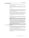
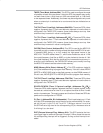
BPCON (Breakpoint Control, Address A9
H
): This SFR controls whether or
not breakpoints are enabled and, if they are, what the source of the breakpoint
is.
BPL/BPH (Breakpoint Address Low/High Byte, Addresses AA
H
/AB
H
):
These two SFRs hold a 16-bit address at which a breakpoint will be triggered.
Which breakpoint (0 or 1) the SFRs reference depends on the configuration
of the MCON SFR.
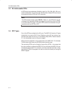
P0DDRL/P0DDRH (Port 0 Data Direction Low/High Byte, Addresses
AC
H
/AD
H
): These two SFRs, together, configure the state of each port 0 pin:
standard 8051 (pull-up), CMOS output, ppen-drain output, or input.
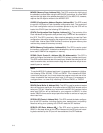
P1DDRL/P1DDRH (Port 1 Data Direction Low/High Byte, Addresses
AE
H
/AF
H
): These two SFRs, together, configure the state of each port 1 pin:
standard 8051 (pull-up), CMOS output, open-drain output, or input.
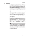
P3 (Port 3, Address B0
H
, Bit-Addressable): This is input/output port 3. Each
bit of this SFR corresponds to one of the pins on the microcontroller. For exam-
ple, bit 0 of port 3 is pin P3.0, bit 7 is pin P3.7. Writing a value of 1 to a bit of
this SFR will set a high level on the corresponding I/O pin, whereas a value of
0 will bring it to a low level.
P2DDRL/P2DDRH (Port 2 Data Direction Low/High Byte, Addresses
B1
H
/B2
H
): These two SFRs, together, configure the state of each port 2 pin:
standard 8051 (pull-up), CMOS output, open-drain output, or input.
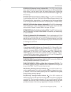
P3DDRL/P3DDRH (Port 3 Data Direction Low/High Byte, Addresses
B3
H
/B4
H
): These two SFRs, together, configure the state of each port 3 pin:
standard 8051 (pull-up), CMOS output, open-drain output, or input.
IP (Interrupt Priority, Addresses B8
H
, Bit-Addressable): This SFR is used
to specify the relative priority of each interrupt. An interrupt may either be of
low (0) priority or high (1) priority. An interrupt may only interrupt interrupts of
lower priority. For example, if we configure the MSC1210 so that all interrupts
are of low priority except the serial interrupt, the serial interrupt will always be
able to interrupt the system, even if another interrupt is currently executing.
However, if a serial interrupt is executing, no other interrupt will be able to inter-
rupt the serial interrupt routine, because the serial interrupt routine has the
highest priority.


