


Setting the Serial Port Baud Rate
9-13
Serial Communication
9.3 Setting the Serial Port Baud Rate
Once the serial port mode has been configured, as explained above, the pro-
gram must configure the serial port baud rate. In mode 0, the baud rate is either
the clock frequency divided by 12 or the clock frequency divided by 4, depend-
ing on the SM2 bit in the SCONx register.
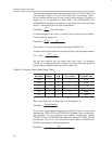
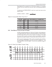
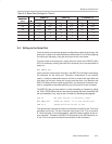
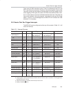
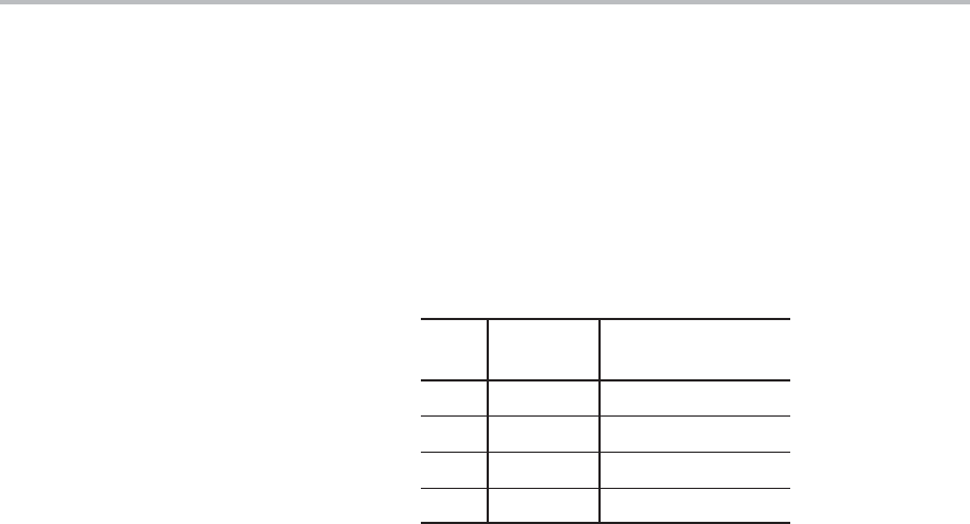
Table 9−4 shows some commonly used baud rates for Mode 0.
Table 9−4.Mode 0 Commonly Used Baud Rates.
SM2
f
OSC
(MHz)
Baud Rate
(kBaud)
0 33 2750
1 33 8250
0 12 1000
1 12 3000
The mode 1 baud rate is a function of timer overflow. Serial Port 0 can use ei-
ther Timer 1 or Timer 2 to generate baud rates. Serial Port 1 can only use Timer
1. The two serial ports can run at the same baud rate if they both use Timer
1, or different baud rates if Serial Port 0 uses Timer 2 and Serial Port 1 uses
Timer 1.
Each time the timer increments from its maximum count (FF
H
for Timer 1 or
FFFF
H
for Timer 2), a clock is sent to the baud-rate circuit. The clock is then
divided by 16 to generate the baud rate. When using Timer 1, the SMOD0 (or
SMOD1) bit selects whether or not to divide the Timer 1 rollover rate by two.
In modes 1 and 3, the baud rate is determined by how frequently Timer 1 or
Timer 2 overflows. The more frequently Timer 1 overflows, the higher the baud
rate. There are many ways you can cause Timer 1 to overflow at a rate that
determines a baud rate, but the most common method is to put Timer 1 in 8-bit
auto-reload mode (Timer mode 2) and set a reload value (TH1) that causes
Timer 1 to overflow at a frequency appropriate to generate a baud rate.
To determine the value that must be placed in TH1 to generate a given baud
rate, the following equation can be used (assuming PCON.7 is clear):
TH1 = 256 − ((Crystal / 384) / Baud)
If PCON.7 is set, the baud rate is effectively doubled, thus, the equation be-
comes:
TH1 = 256 − ((Crystal / 192) / Baud)