Analog-to-Digital Converter
17-19
Keil Simulator
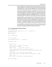
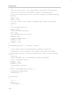
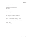
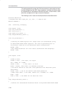
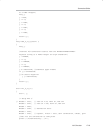
SIGNAL void a_to_d_sim (void)
{
inti;
/*Data written into the variable ain0 is automatically
entered into the editable text window labeled AIN0 in
the ADC peripheral dialog.*/
ain0 = 0.5; //specify start value for ain0
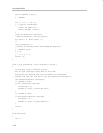
//debug program idles for 196000 clock cycles, while
simulation continues running in parallel*/
twatch (196000);
/*the following loop sends out 64 consecutive samples
of ain0,each incremented by 0.01. Each transmittal is
spaced 131000 clock cycles from the previous one.*/
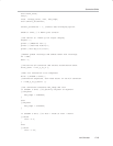
for (i = 0; i < 0x40; i++)
{
twatch (900);
ain0 += 0.01;
twatch (130100);
}
}
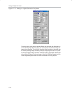
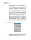
The reference voltages are also specified through the VREFP and VREFN
editable text windows. Checks to evaluate the validity of the values placed in
these windows are also implemented. Should the difference between the val-
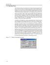
ue in VREFP and VREFN exceed 2.5V, the error message in Figure 17−9 is
displayed.
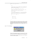
Figure 17−9. Error Message
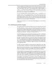
The value of internal reference voltage, which is based on the status of the
VREFH bit of the ACDON0 SFR, is displayed on the non-editable V
REF
window.
Please refer to Chapter 12, Analog-to-Digital Converter, for more in-depth dis-
cussions on the pertinent registers.


