


Serial Peripheral Interface (SPI)
17-35
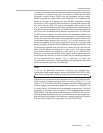
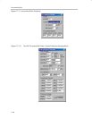
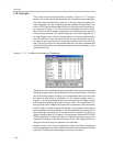
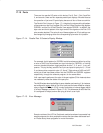
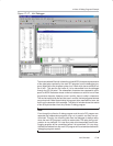
Keil Simulator
#include ”MSC1210.H”
//unsigned char data irqen_init _at_ 0x7f ; // image of PAI
#define FWVer 0x04
#define CONVERT 0
char received_data[50];
void init_spi ();
void transmit_receive ();// interrupt 6;
void test_spi ();
void test_spi ()
{
SPIDATA = 55;
while (1);
}
void setport (void)
{
P3DDRL &= 0xf0;
P3DDRL |= 0x07; //P30 input, P31 output
TF2 = CLEAR; T2 = CLEAR;
CKCON |= 0x20; // Set timer 2 to clk/4
RCAP2 = 0xffd9; //Set Timer 2 to Generate 57690 bps
//Initialize TH2:TL2 so that next clock generates first Baud Rate pulse
THL2=0xffff;
T2CON = 0x34; // Set T2 for Serial0 Tx/Rx baud generation
//SCON: Async mode 1, 8−bit UART, enable rcvr; TI=CLEAR, RI = CLEAR
SCON = 0x50;
PCON |= 0x80; // Set SMOD0 for 16X baud rate clock
}
void init_spi ()
{
/*enable SPI, specify Master SPI and specify clock rate, (Fosc / 32)
and CPHA = 1*/
SPICON = 0x96;
/*Flush receive buffer, and set IRQ level to 2*/
SPIRCON = 0x81;
/*Flush transmit buffer, and set IRQ level to 4*/
SPITCON = 0x82;
/*buffer start address = 0x0ao, and end address = 0x0b0*/
SPISTRT = 0x0a0;