


Installation
3–24 976-0043-01-02
Procedure for Dual-Inverter Systems
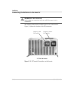
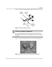
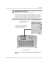
Before starting this procedure, please review Figure 3-10, “DC Terminal
Connections on the Inverter” on page 3–20 and Figure 3-11, “Battery
Cable Connection” on page 3–21 for the locations of the terminals and
details on attaching positive (+) and negative (–) cables to terminals on
the inverter DC end. Ensure the unit is properly grounded before
proceeding.
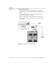
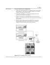
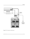
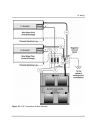
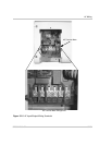
While performing the following procedure, please refer to Figure 3-14.
Use the following procedure to connect the battery (or battery bank)
to the inverters.
1. Connect POSITIVE cables:
a) one cable from the battery POSITIVE terminal to a circuit
breaker in the DC disconnect (torque to manufacturer’s recom-
mendations). The DC disconnect should be located as close to the
batteries as possible.
b) a second cable from the same battery POSITIVE terminal to
another circuit breaker in the DC disconnect.
c) a third cable from the first circuit breaker in the DC disconnect to
the L1 inverter POSITIVE (+) terminal.
d) a fourth cable from the second DC disconnect to the L2 inverter
POSITIVE (+) terminal.
2. Connect NEGATIVE cables:
a) one cable from the same battery NEGATIVE terminal (torque to
manufacturer’s recommendations) to the ground bond in the DC
disconnect.
b) a second cable from the same battery NEGATIVE terminal
(torque to manufacturer’s recommendations) to the ground bond
in the DC disconnect.
c) a third one from the ground bond in the DC disconnect to the L1
inverter NEGATIVE (–) terminal.
d) a fourth one from the ground bond in the DC disconnect to the
L2 inverter NEGATIVE (–) terminal.
3. Ensure the correct polarity of the cables with a DC voltmeter (DVM).
4. Use an insulated 1/2 inch wrench or socket to tighten the 5/16 SAE
nuts to 10-15 foot/lb for each inverter input terminal.
5. Apply antioxidant paste to the battery terminals, if desired.
6. Install the battery terminal covers (if used)—red for positive, black
for negative—over the inverter DC terminals and secure with the
screws and washers provided.