


Menu Item Descriptions
976-0043-01-02 7–21
23E RY10 Vdc DeEnergized
This menu item sets the trip point where the relay de-energizes. When the
voltage, based on the 04B Battery Comp VDC display, drops to or below
this setting, the relay de-energizes and opens the contacts between the
N.O. and COM terminals immediately. There is no time delay on the
reaction of this setting, allowing fast response to rapid voltage changes in
the system. This setting is temperature compensated when a BTS is
installed and operates in both inverter and charger modes.
23F RY10 Delay at Engz. Min
This menu item sets the delay time period in minutes at which the voltage
level must remain at or below before relay RY10 is deenergized. This is
an “active low” type of control. The relay closes when the battery voltage
falls to or below the level set in menu 23E RY10 VDC DeEnergized for
the time period set here.
23G RY11 Mode
These two settings allow the RY11 relay in the ALM or GSM to function
differently based on your selection.
Cooldown In a multiple Sine Wave Plus inverter installation and using
the inverter’s automatic generator feature, you can use the cooldown
selection to enable an external contactor to allow both legs of a generator
to go through a cooldown period.
When using the generator “AUTO” selection and connecting two
inverters in a “series-stacked” installation (for 120/240Vac operation), the
inverter that controls the generator will disconnect from the generator to
allow a cooldown period prior to stopping the generator. The other
inverter not controlling the generator does not know the generator is about
ready to be stopped; so it cannot disconnect from the generator to allow
this leg a cooldown period. Selecting “cooldown” under RY11 mode and
using the RY11 relay to control an external contactor - that feeds both
inputs to the inverters - will allow both legs of the generator to be
disconnected and unloaded at the same time and go thru the cooldown
period prior to shutting down.
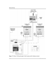
See Figure 7-3 on page 7–22 for the installation diagram using this
feature.
Error This selection allows the RY11 relay to function as an Error
Detection Relay. The blue LED (controlled by the RY11 relay) on the
GSM or ALM is on to indicate that the inverter is on (or in SCRCH
mode). If the blue LED does not turn on, the inverter is not powered (or
OFF), is in CHR mode or there is an error condition.