


Menu Item Descriptions
976-0043-01-02 7–31
RN1 This selection provides a run signal by holding the RY7 relay
closed between contacts N.O. and COM. and requires the AC generator
output to be monitored by the inverter’s AC2 input.
RN2 This selection provides a run signal by holding the RY7 relay
closed between contacts N.O. and COM. but does not require the
generator output to be monitored by the AC2 terminal. This selection can
allow the DC generator to be started/stopped by the inverter.
Guidelines for setting this menu item:
• Many diesel generators provide their own glow and stop signals as
well as powering the glow plugs during the cranking signal period.
Check with the generator’s manufacturer for specific details.
• The RN1 setting requires AC2 input to sense the generator output to
stop cranking.
• The RN2 setting does NOT require AC2 input to sense the generator
output to stop cranking.
• When either RN1 or RN2 is selected as the function of the RY7 relay,
the RY7 COM and RY7 N.O. contacts remain closed while the
generator is running. The RY7 N.C. (Normally Closed) contact is
open (not connected to the common terminal) while the generator is
running.
• When the generator is off, the RY7 N.C. terminal is connected to the
RY7 COM terminal. This configuration is useful for starting a two
wire (auto-crank) type generator.
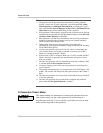
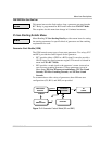
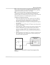
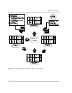
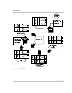
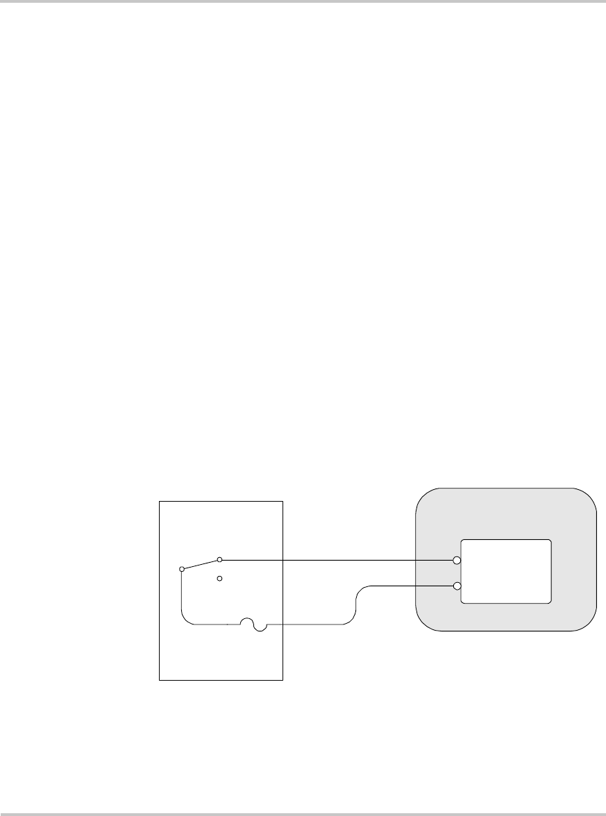
Figure 7-6
RY7’s COM and N.O. Contacts Close (energize) to Run
Generator
GSM
COM
N.O.
N.C.
RY7
REMOTE START/
STOP
TERMINALS
5 AMP
FUSE
2-WIRE START TYPE
GENERATOR