


Figures
976-0043-01-02 xxi
Figure 5-13 Advanced Setup Menu Map Part 1 - - - - - - - - - - - - - - - - - - - - - - - - - - -5–12
Figure 5-14 Advanced Setup Menu Map Part 2 - - - - - - - - - - - - - - - - - - - - - - - - - - -5–13
Figure 5-15 Complete User Menu Map- - - - - - - - - - - - - - - - - - - - - - - - - - - - - - - - - 5–14
Figure 5-16 Complete Basic Setup Menu Map - - - - - - - - - - - - - - - - - - - - - - - - - - - - 5–15
Figure 5-17 Complete Advanced Setup Menu Map- - - - - - - - - - - - - - - - - - - - - - - - - 5–16
Figure 6-1 Accessing the Basic Setup Menu - - - - - - - - - - - - - - - - - - - - - - - - - - - - 6–10
Figure 6-2 Multi-Stage Battery Charging Process - - - - - - - - - - - - - - - - - - - - - - - - - 6–16
Figure 7-1 Accessing the Advanced Setup Menu - Method 1 - - - - - - - - - - - - - - - - - 7–11
Figure 7-2 Accessing the Advanced Setup Menu - Method 2 - - - - - - - - - - - - - - - - - 7–12
Figure 7-3 Relay 11 Wiring Example to Dual Inverters with Cooldown selected - - - -7–22
Figure 7-4 Generator Control Mode (GS and RN1)- - - - - - - - - - - - - - - - - - - - - - - - 7–29
Figure 7-5 Generator Control Mode (RN2) - - - - - - - - - - - - - - - - - - - - - - - - - - - - - 7–30
Figure 7-6 RY7’s COM and N.O. Contacts Close (energize) to Run Generator - - - - - 7–31
Figure 7-7 Wiring examples of Honda™ and Onan™ Generators - - - - - - - - - - - - - -7–33
Figure 7-8 RY7 and RY8 Timing Diagram - - - - - - - - - - - - - - - - - - - - - - - - - - - - - 7–34
Figure 7-9 RY7/RY8 Sequence of Events for RN1 or RN2 Selection- - - - - - - - - - - - 7–35
Figure 7-10 RY7/RY8 Sequence of Events for GS Selection - - - - - - - - - - - - - - - - - - 7–36
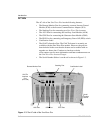
Figure 8-1 LED Indicators - - - - - - - - - - - - - - - - - - - - - - - - - - - - - - - - - - - - - - - - -8–3
Figure 8-2 Inverter Operation Status LEDs - - - - - - - - - - - - - - - - - - - - - - - - - - - - - -8–4
Figure 8-3 AC Status LEDs - - - - - - - - - - - - - - - - - - - - - - - - - - - - - - - - - - - - - - - -8–5
Figure 8-4 Charge Status LEDs - - - - - - - - - - - - - - - - - - - - - - - - - - - - - - - - - - - - - -8–6
Figure 8-5 Error and Status LEDs - - - - - - - - - - - - - - - - - - - - - - - - - - - - - - - - - - - -8–7
Figure 8-6 Inverter ON/OFF Display - - - - - - - - - - - - - - - - - - - - - - - - - - - - - - - - -8–14
Figure 8-7 Generator ON/OFF Display - - - - - - - - - - - - - - - - - - - - - - - - - - - - - - - - 8–14
Figure 8-8 Resetting Factory Default Settings - - - - - - - - - - - - - - - - - - - - - - - - - - -8–21
Figure A-1 Sine Wave Plus Simple Block Diagram - - - - - - - - - - - - - - - - - - - - - - - - A–6
Figure A-2 Sine Wave Plus Inverter Output Waveform - - - - - - - - - - - - - - - - - - - - - A–7
Figure A-3 Power Versus Efficiency Curves for All Models - - - - - - - - - - - - - - - - - - A–9
Figure A-4 Sine Wave Plus Efficiency Curve for the SW Plus 2524- - - - - - - - - - - - - A–9
Figure A-5 Sine Wave Plus Efficiency Curve for the SW Plus 2548 - - - - - - - - - - - - A–10
Figure A-6 Sine Wave Plus Efficiency Curve for the SW Plus 4024 - - - - - - - - - - - - A–10
Figure A-7 Sine Wave Plus Efficiency Curve for the SW Plus 4048 - - - - - - - - - - - - A–11
Figure A-8 Sine Wave Plus Efficiency Curve for the SW Plus 5548 - - - - - - - - - - - - A–11
Figure A-9 Time versus Current for the Sine Wave Plus 2524- - - - - - - - - - - - - - - - A–13
Figure A-10 Time versus Current for the Sine Wave Plus 2548 - - - - - - - - - - - - - - - - A–14
Figure A-11 Time versus Current for the Sine Wave Plus 4024 - - - - - - - - - - - - - - - - A–14